
Liquid supply system

A liquid supply and liquid technology, applied in the direction of liquid displacement machinery, refrigeration and liquefaction, lighting and heating equipment, etc., can solve problems such as difficult high pressure, bellows buckling, etc., to suppress buckling, improve pump function, and improve stability sexual effect

Active Publication Date: 2017-05-10
EAGLE INDS
View PDF5 Cites 0 Cited by
  • Summary
  • Abstract
  • Description
  • Claims
  • Application Information

AI Technical Summary

Problems solved by technology

However, the structure of the conventional volumetric bellows circulator applies internal pressure to the bellows, so it is difficult to increase the pressure
In addition, when a high discharge pressure is applied as the internal pressure of the bellows, the bellows will buckle

Method used


Image

  • Liquid supply system
  • Liquid supply system
  • Liquid supply system

Examples


Embodiment 1

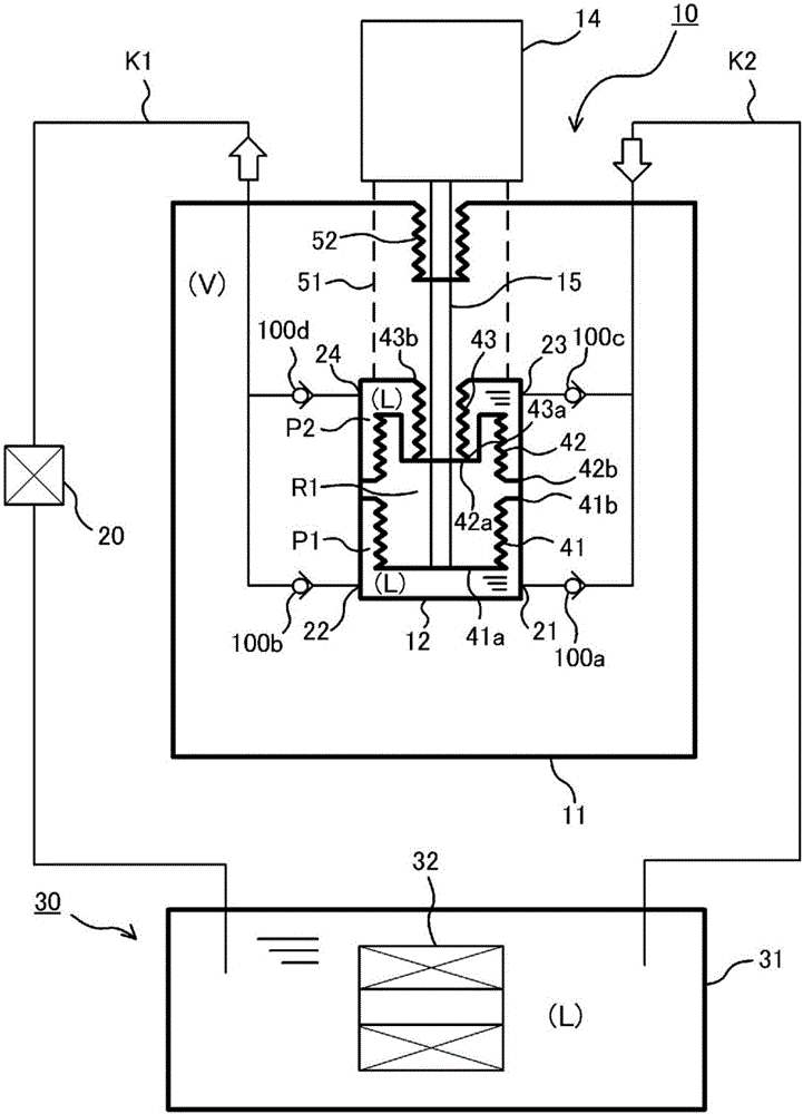
[0040] refer to figure 1 , the liquid supply system of the embodiment of the present invention will be described. figure 1 is a schematic configuration diagram of a liquid supply system according to an embodiment of the present invention.

[0041] The liquid supply system 10 is a pump device for cryogenic fluid, and in order to keep the superconducting cable 32 in the cooling device 30 equipped with the superconducting cable 32 inside the resin container 31, it is continuously supplied to the container. The ultra-low temperature liquid L is supplied in 31 . Specific examples of the cryogenic liquid L include liquid nitrogen and liquid helium.

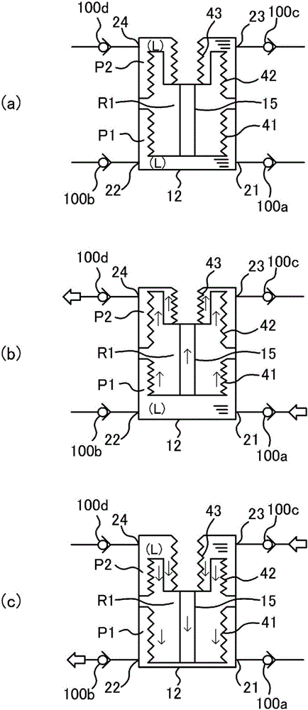
[0042] The liquid supply system 10 roughly includes a first container (outer container) 11 with a vacuum inside, and a second container 12 arranged inside the first container 11 and surrounded by a vacuum space. In the second container 12 , three bellows 41 , 42 , 43 are arranged in series in respective expansion and contraction di...

Embodiment 2

[0063] In the first embodiment described above, the closed space R1 is a vacuum space, but in the second embodiment of the present invention, the closed space R1 is filled with gas. The other configurations are the same as those in Embodiment 1, and the same reference numerals are assigned to the same configurations, and description thereof will be omitted.

[0064] As the gas enclosed in the closed space R1, for example, neon gas, helium gas, etc., which are unlikely to undergo state changes such as liquefaction and freezing in the operating environment of this system, are used. In addition, the pressure of the gas enclosed in the closed space R1 is set to a range from vacuum (-100 kPa) to a required discharge pressure (preferably 1 / 2 of the discharge pressure).

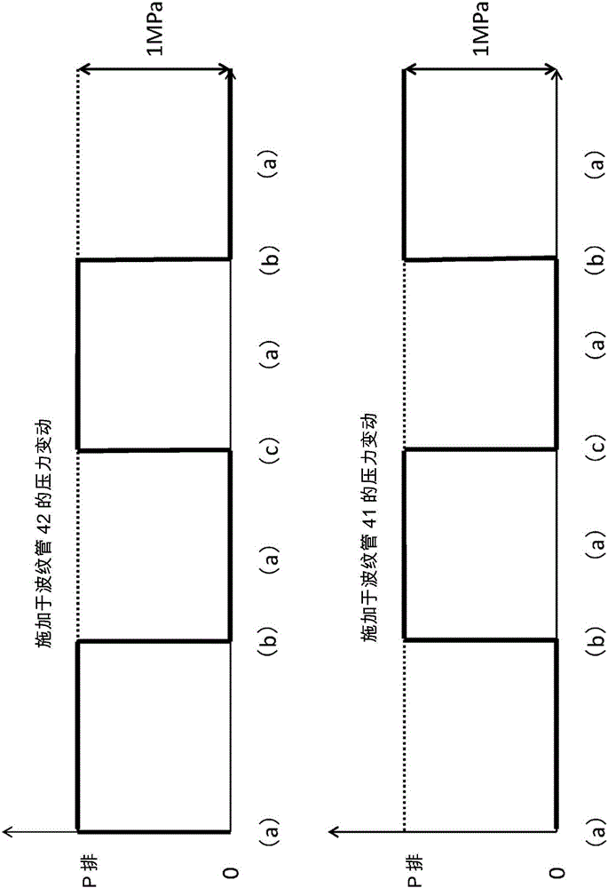
[0065] Figure 4 It is a graph roughly showing the variation of the discharge pressure of the liquid supply system of the second embodiment, the upper half shows the variation of the pressure applied to the bellows 4...


PUM


Abstract

Provided is a liquid supply system with an improved pumping function. The liquid supply system includes first and second bellows 41 and 42 arranged in series in an expanding / contracting direction thereof in a vessel 12 and having first end portions respectively, which are close to each other and fixed to an inner wall of the vessel 12, and also having second end portions respectively, which are distant from each other and movable in the expanding / contracting direction. An inner space of the vessel 12 located outside the first bellows 41 serves as a first pump chamber P1. An inner space of the vessel 12 located outside the second bellows 42 serves as a second pump chamber P2. An inner space of the vessel 12 located inside the first and second bellows 41 and 42 serves as a sealed space R1. A shaft 15 to which the respective second end portions of the first and second bellows 41 and 42 are fixed is reciprocally moved to expand / contract the first and second bellows 41 and 42.

Description

technical field [0001] The invention relates to a liquid supply system for supplying ultra-low temperature liquids such as liquid nitrogen and liquid helium. Background technique [0002] Conventionally, there is known a technique of supplying a cryogenic liquid such as liquid nitrogen to a vacuum insulated tube housing a superconducting cable and the like to maintain the superconducting cable and the like in a cryogenic state. In the liquid supply (circulation) system of the cryogenic liquid, in order to keep the superconducting cable in a superconducting state in the cooling device equipped with the superconducting cable inside the vacuum insulating pipe, the cryogenic liquid is continuously supplied into the vacuum insulating pipe. [0003] The length of conventional superconducting cables is short, and the discharge pressure required by the liquid supply system can be satisfied with a relatively low discharge pressure relative to the flow rate. Therefore, a typical centr...

Claims


Application Information

Patent Timeline
Patent Type & Authority Applications(China)
IPC IPC(8): F25B9/00F04B15/08F04B43/08
CPCF04B43/08F25B9/00F04B43/088F04B45/024F04B15/08F04B43/084F04B2015/081
Inventor 森浩一大泽芳夫古田清隆
Owner EAGLE INDS
Learn More