Municipal drainage pipeline

A municipal drainage and pipeline technology, applied in the field of municipal drainage pipelines, can solve the problems of blockage, difficulty in completely cleaning the waste layer, and low cleaning efficiency.

Active Publication Date: 2021-07-30
湖南沃开节能科技有限公司
View PDF5 Cites 4 Cited by
  • Summary
  • Abstract
  • Description
  • Claims
  • Application Information

AI Technical Summary

Problems solved by technology

[0002] Municipal drainage pipes refer to the rainwater and sewage pipes under the municipal roads, commonly known as "sewer pipes", which are usually called municipal drainage pipes in engineering. In the drainage pipes, the accumulation of silt or garbage is a common phenomenon, especially in the tee Or the pipes at ...

Method used


Image

  • Municipal drainage pipeline
  • Municipal drainage pipeline
  • Municipal drainage pipeline

Examples


specific Embodiment approach 1

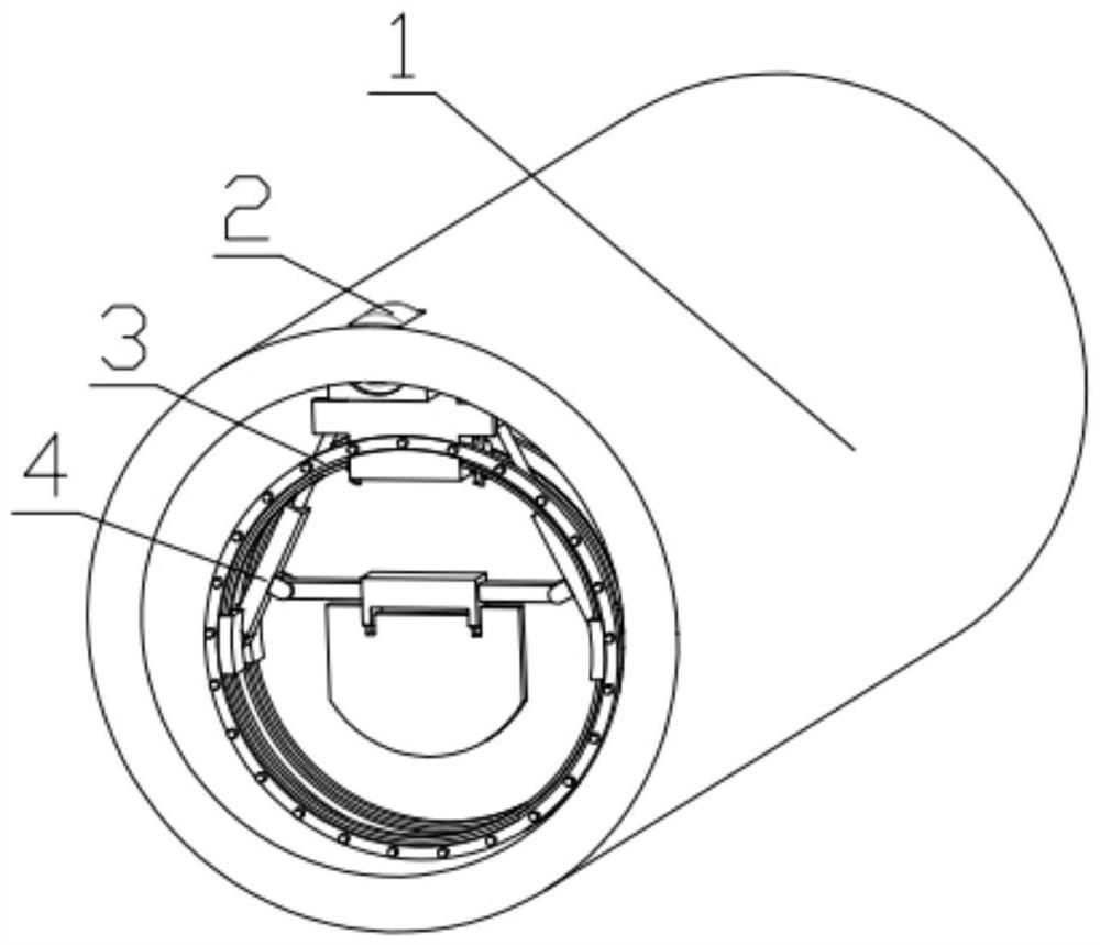
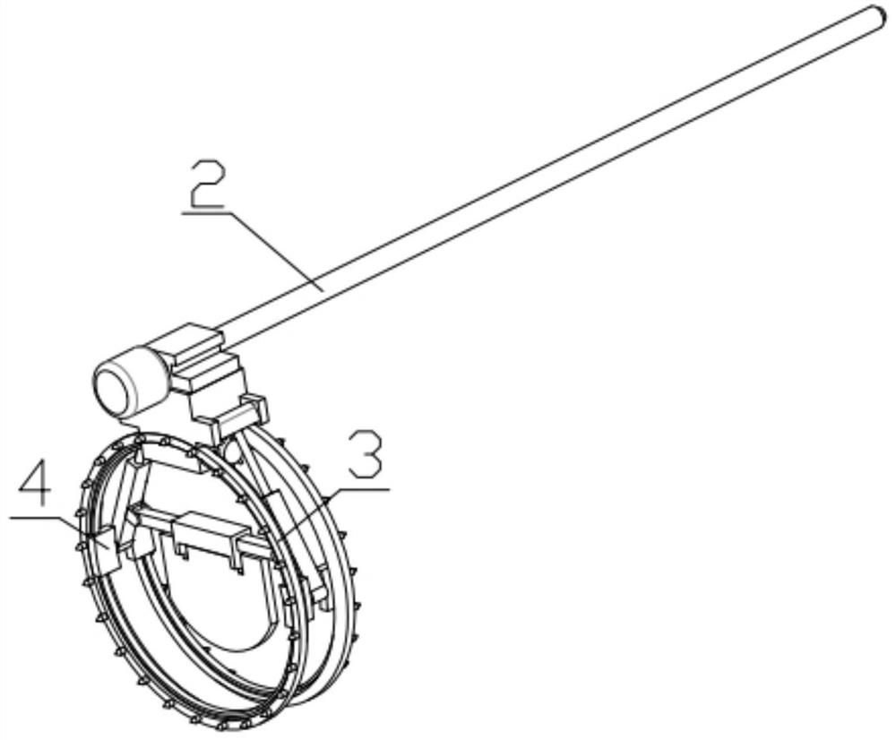
[0029] Combine below Figure 1-11 Describe this embodiment, a municipal drainage pipeline, including a pipe fitting 1, a displacement assembly 2, a surrounding cleaning mechanism 3 and a repairing and pushing mechanism 4, the displacement assembly 2 is fixedly installed on the pipe fitting 1, and the surrounding cleaning mechanism 3 is fixedly installed on the On the displacement assembly 2, the repairing and pushing mechanism 4 is slidably installed on the surrounding cleaning mechanism 3.

specific Embodiment approach 2

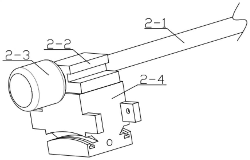
[0031] Combine below Figure 1-11 Describe this embodiment, this embodiment will further explain the first embodiment, the displacement assembly 2 includes a threaded rod 2-1, a limit block 2-2, a displacement motor 2-3, a connecting shell 2-4, and a displacement The motor 2-3 is fixedly installed in the groove provided on the pipe fitting 1, the output end of the displacement motor 2-3 is fixedly installed with a threaded rod 2-1, and the threaded rod 2-1 is rotatably installed in the groove provided on the pipe fitting 1 , the threaded rod 2-1 is threadedly connected with the limit block 2-2, the limit block 2-2 is slidably installed in the groove provided on the pipe fitting 1, and the connection shell 2-4 is fixedly installed on the limit block 2-2.

specific Embodiment approach 3

[0033] Combine below Figure 1-11 Describe this embodiment, this embodiment will further explain the second embodiment, the surrounding cleaning mechanism 3 includes a cleaning motor 3-1, a cleaning ring 3-2, a main helical gear 3-3, and an auxiliary helical gear 3-4 , driven helical gear 3-5, connecting short bar 3-6, cleaning brush 3-7, and cleaning motor 3-1 is fixedly installed in the groove that is provided with on the connection shell 2-4, and cleaning motor 3-1 The main helical gear 3-3 is fixedly installed on the output end, the auxiliary helical gear 3-4 is fixedly installed on the main helical gear 3-3, the main helical gear 3-3 meshes with the cleaning ring 3-2, and the cleaning ring 3-2 slides Installed in the groove provided on the connection shell 2-4, the auxiliary helical gear 3-4 meshes with the driven helical gear 3-5, and the driven helical gear 3-5 is rotated and installed in the groove provided on the connection shell 2-4. In the groove, the driven helica...


PUM


Abstract

The invention relates to the related field of municipal drainage, in particular to a municipal drainage pipeline. The municipal drainage pipeline comprises a pipe fitting, a displacement assembly, a surrounding and cleaning mechanism and a repairing and pushing mechanism, wherein the displacement assembly is fixedly mounted on the pipe fitting, the surrounding and cleaning mechanism is fixedly mounted on the displacement assembly, and the repairing and pushing mechanism is slidably mounted on the surrounding and cleaning mechanism. The municipal drainage pipeline has the function of cleaning accumulated sludge in the pipeline, can clean stubborn sludge, ensures the smoothness of the pipeline, has the function of pushing the sludge, and can accelerate the cleaning speed.

Description

technical field [0001] The invention relates to the related field of municipal drainage, more specifically a municipal drainage pipeline. Background technique [0002] Municipal drainage pipes refer to the rainwater and sewage pipes under the municipal roads, commonly known as "sewer pipes", which are usually called municipal drainage pipes in engineering. In the drainage pipes, the accumulation of silt or garbage is a common phenomenon, especially in the tee Or the pipes at the four-way, the accumulation phenomenon is obvious, and after long-term use, there will be clogging and other situations. When manually cleaning regularly, it needs to be cleaned section by section with the help of water guns or shovels. The cleaning efficiency is low and it is difficult to completely clean the waste layer. Contents of the invention [0003] The main technical problem to be solved by the present invention is to provide a municipal drainage pipe. The device has the function of cleanin...

Claims


Application Information

Patent Timeline
IPC IPC(8): E03F3/04E03F3/06E03F9/00
CPCE03F3/04E03F3/06E03F9/002E03F2003/065
Inventor 陈杨
Owner 湖南沃开节能科技有限公司
Why Eureka
Try Eureka