
A kind of automobile and its shift handle assembly

A technology for shifting and shifting handles of automobiles, which is applied to components with teeth, belts/chains/gears, mechanical equipment, etc., and can solve problems such as easy-to-error shift positions, inconspicuous changes in shifting feel, and car damage. To achieve the effect of avoiding the wrong gear

Active Publication Date: 2017-02-01
BEIJING CHANGAN AUTOMOBILE ENG TECH RES
View PDF6 Cites 0 Cited by
  • Summary
  • Abstract
  • Description
  • Claims
  • Application Information

AI Technical Summary

Problems solved by technology

[0003] In the prior art, the gearshift handle includes a handle ball and a shift rod core matched with the handle ball. A slider is arranged inside the handle ball, an unlock button is arranged at one end of the slider, and a button is arranged between the other end and the inner wall of the handle ball. Reset device, the bottom of the slider is provided with a groove with a slope at the top, and the top of the shift lever core is in contact with the top of the groove. When in use, the motion of the slider in the handle ball is transformed through the slope at the top of the groove For the movement of the shift rod core along its own length direction, the gear block on the gear shift rod core avoids the stop step surface on the gear platform, so as to achieve the purpose of unlocking, but the structure of this structure The shift handle, during the pressing of the unlock button, the change of the shift feel is not obvious, and it is easy to mistake the shift position and cause damage to the car

Method used


Image

  • A kind of automobile and its shift handle assembly
  • A kind of automobile and its shift handle assembly
  • A kind of automobile and its shift handle assembly

Examples


Embodiment Construction

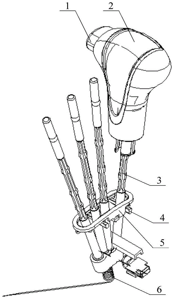
[0021] The invention provides an automobile and its gearshift handle assembly to achieve the purpose of making the driver's hand feel change significantly when shifting gears and avoiding wrong gear shifting without affecting the smoothness of gear shifting.

[0022] The following will clearly and completely describe the technical solutions in the embodiments of the present invention with reference to the accompanying drawings in the embodiments of the present invention. Obviously, the described embodiments are only some, not all, embodiments of the present invention. Based on the embodiments of the present invention, all other embodiments obtained by persons of ordinary skill in the art without making creative efforts belong to the protection scope of the present invention.

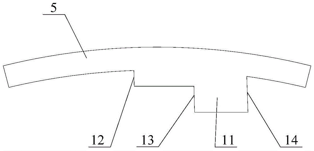
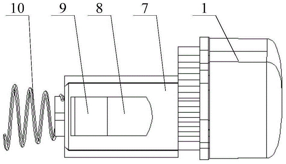
[0023] see Figure 1-Figure 3 , figure 1 Schematic diagram of the structure of the automobile shift handle assembly provided by the embodiment of the present invention; figure 2 The front view of the ...


PUM


Abstract

The invention discloses a car gear shifting handle assembly. A sliding block and a reset device are arranged in a handle ball, an unlocking button and the reset device are arranged at the two ends of the sliding block respectively, a groove is formed in the lower portion of the sliding block, and the top face of the groove at least comprises a first inclined face and a second inclined face different in slope. One end of a gear shifting rod core abuts against the top face of the groove, a return device is arranged at the other end of the gear shifting rod core, and a gear block is arranged on the gear shifting rod core. A long groove allowing the rod core to penetrate and backstop step surfaces matched with the gear block are arranged on a gear table, and the backstop step surfaces at least comprise three backstop step surfaces carrying out gear shifting limiting on a gear P, a gear N to a gear R and the gear R to the gear P respectively. Due to the fact that the two inclined faces at the top of the groove are different in slope, and in the process of switching the gear P, the gear N to the gear R and the gear R to the gear P, the touch feelings of a driver are completely different when the driver presses the unlocking button, the driver can direct know the gear state through the touch feelings, the gears are prevented from being shifted wrongly, and gear shifting smoothness cannot be influenced. The invention further discloses a car.

Description

technical field [0001] The invention relates to the technical field of automobiles, in particular to an automobile and its shift handle assembly. Background technique [0002] At present, a safety device is usually integrated on the shift handle of the car, which is used to unlock the P gear and the R gear when switching between the P gear and the R gear. [0003] In the prior art, the gearshift handle includes a handle ball and a shift rod core matched with the handle ball. A slider is arranged inside the handle ball, an unlock button is arranged at one end of the slider, and a button is arranged between the other end and the inner wall of the handle ball. Reset device, the bottom of the slider is provided with a groove with a slope at the top, and the top of the shift lever core is in contact with the top of the groove. When in use, the motion of the slider in the handle ball is transformed through the slope at the top of the groove For the movement of the shift rod core ...

Claims


Application Information

Patent Timeline
Patent Type & Authority Patents(China)
IPC IPC(8): F16H59/02
CPCF16H59/0278F16H59/10F16H61/24F16H2059/026F16H2059/0295F16H2061/241
Inventor 孙晓伟王超张海成展立均吴礼军陈士昌
Owner BEIJING CHANGAN AUTOMOBILE ENG TECH RES
Learn More