Large cylindrical part dovetail groove machining method

A processing method and technology of dovetail grooves, applied in metal processing equipment, metal processing mechanical parts, manufacturing tools, etc., can solve problems affecting product accuracy, machine tool accuracy and poor rigidity, vibration, etc., to avoid vibration, ensure position accuracy and The effect of dimensional accuracy

Inactive Publication Date: 2021-08-31
CHINA ERZHONG GRP DEYANG HEAVY IND
View PDF12 Cites 0 Cited by
  • Summary
  • Abstract
  • Description
  • Claims
  • Application Information

AI Technical Summary

Problems solved by technology

The realization of this processing method needs to meet at least two conditions: first, it needs to be equipped with a high-precision rotary table to ensure the accuracy of the rotation angle, so as to ensure the position of the dovetail groove in the circumferential distribution; second, the machine tool must be at Y=0 The range of ~3000mm has good precision to ensure the straightness and verticality of the dovetail groove axis. The farther the machine tool ram is from the platform, the worse the precision and rigidity of the machine tool, and the resulting vibration and other phenomena are extremely obvious. , which seriously affects the product accuracy
Therefore, this processing method has great limitations. In the case of high precision machine tools, it can only process dovetail grooves of cylindrical parts with a total length of no more than 3 meters.

Method used


Image

  • Large cylindrical part dovetail groove machining method
  • Large cylindrical part dovetail groove machining method
  • Large cylindrical part dovetail groove machining method

Examples


Embodiment Construction

[0034] The present invention will be further described below in conjunction with the accompanying drawings and embodiments.

[0035] The method for processing dovetail grooves of large cylindrical parts of the present invention comprises

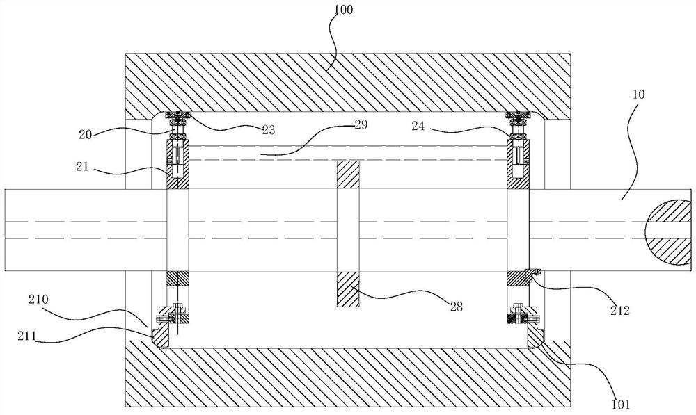
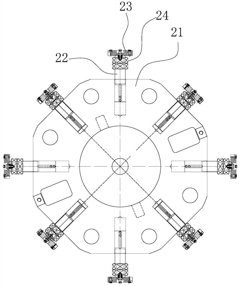
[0036] Put the mandrel device into the cylindrical part 100, such as figure 1 As shown, the mandrel device includes a mandrel 10 and a support member 20 arranged on the mandrel 10, the support member 20 is in press contact with the inner wall of the cylindrical part 100, and the two ends of the mandrel 10 protrude from the cylindrical part. 100 parts.

[0037] The mandrel 10 has a central through hole, the length of which is greater than the length of the cylindrical part 100, so that after the mandrel 10 passes through the cylindrical part 100, the two ends of the mandrel 10 can be located outside the cylindrical part 100, so as to align the mandrel 10 two ends carry out clamping. The support member 20 is used to fix the cylindrical part...


PUM


Abstract

The invention provides a large cylindrical part dovetail groove machining method. The large cylindrical part dovetail groove machining method comprises the steps that a core shaft device is placed in a cylindrical part, the core shaft device comprises a core shaft and a supporting part arranged on the core shaft, the supporting part makes contact with the inner wall of the cylindrical part in a pressing mode, and the two ends of the core shaft extend out of the cylindrical part; a formwork is installed on the end face of the cylindrical part, the formwork is coaxial with the cylindrical part, the outer side wall of the formwork coincides with the outer side wall of the cylindrical part, a plurality of model grooves are formed in the outer side wall of the formwork, and the number, the size and the interval of the model grooves are equal to the number, the size and the interval of dovetail grooves to be machined; and the two ends of the core shaft are clamped, a tool penetrates through one model groove and then is fed in the axial direction of the cylindrical part, machining of the dovetail grooves is completed, then the core shaft is rotated, the next model groove is aligned with the tool, and the next dovetail groove is machined till machining of all the dovetail grooves is completed. The cylindrical part is converted into the shaft part, the clamping difficulty is low, the formwork is used as the machining reference, and the machining precision is high.

Description

technical field [0001] The invention relates to the technical field of dovetail groove processing, in particular to a method for processing dovetail grooves of large cylindrical parts. Background technique [0002] The dovetail grooves in the present invention are axial wire grooves, which are generally evenly distributed in the circumferential direction. The slotting processing of large parts is common in motor rotors, and armature windings are embedded in the slots to realize power generation; there are two main methods for slotting processing: one is to use a special machine to process the slots in a horizontal position; the other is to use a CNC boring machine Machine the wire groove directly above. Due to the long journals at both ends of the motor rotor, the workpiece can be clamped conveniently no matter it is on a special machine or on a CNC boring machine. [0003] Large cylindrical parts do not have a journal similar to that of the motor rotor, and the workpiece ...

Claims


Application Information

Patent Timeline
Patent Type & Authority Applications(China)
IPC IPC(8): B23C3/28B23C9/00B23Q3/12
CPCB23C3/28B23C9/00B23Q3/12
Inventor 谭万斌张金生廖世超阳建军杨年浩刘洁
Owner CHINA ERZHONG GRP DEYANG HEAVY IND
Why Eureka
Try Eureka