High-speed and high-accuracy driving device for rotary table

A technology of rotary table and driving device, which is applied in the direction of transmission device, transmission device parts, manufacturing tools, etc. It can solve the problems of inability to achieve precise speed control, inability to achieve precise indexing, high gear precision requirements, etc., and achieve simple structure, gear The effect of low accuracy requirements and high repeat positioning accuracy

Active Publication Date: 2012-09-05
WEIHAI HUADONG AUTOMATION
View PDF5 Cites 0 Cited by
  • Summary
  • Abstract
  • Description
  • Claims
  • Application Information

AI Technical Summary

Problems solved by technology

[0002] Ordinary vertical lathe rotary table driving device is generally realized by ordinary DC motor driven reduction box, and multi-stage gear reduction is carried out in the reduction box, which requires high gear precision, complicated manufacturing process and high cost
The backlash elimination of gears mostly adopts the mechanical anti-backlash method, which requires high precision of the gears, and the adjustment of the backlash is cumbersome, and the effect is not ideal
Ordinary motors achieve speed control through frequency conversion, which cannot achieve precise speed control, nor can they achieve precise indexing, and the working mode is single

Method used


Image

  • High-speed and high-accuracy driving device for rotary table
  • High-speed and high-accuracy driving device for rotary table
  • High-speed and high-accuracy driving device for rotary table

Examples


Embodiment Construction

[0014] Below in conjunction with accompanying drawing, the utility model is further described:

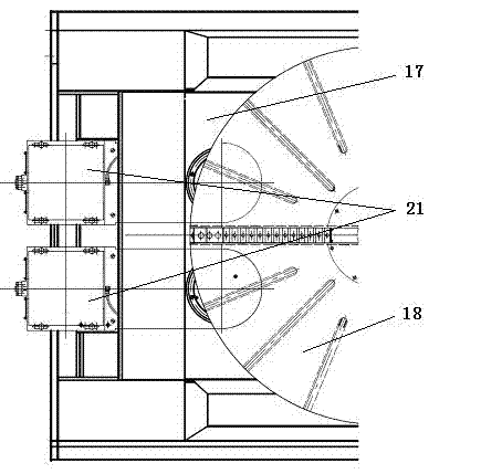
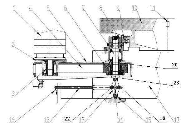
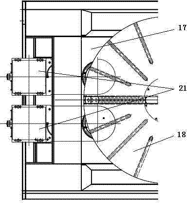
[0015] A high-speed, high-precision rotary workbench driving device is provided with a workbench 1, a base 17 and a control system. Two sets of rotary drive devices 21 are arranged side by side. An angle encoder 11 is provided at the center of the workbench 10. The rotary drive device 21 includes a box body 5, a servo motor 1, an adjustment seat 2, a main drive gear 3, a drive shaft 7, and a drive sprocket. 3 and the driven sprocket 6, the encoder 11 is connected with the control system, the box body 5 is fixed on the base 17, one end of the box body 5 is provided with a positioning sleeve 20, and the other end is provided with an adjustment seat 2, and the inner wall of the positioning sleeve 20 is passed through the bearing It is fixedly connected with the driving shaft 7, the outer wall is fixedly connected with the driven sprocket 6, the driven sprocket 6 is meshed with the syn...


PUM


Abstract

The invention discloses a high-speed and high-accuracy driving device for a rotary table. The driving device provided by the invention is provided with a work table, a base and a control system, wherein the lower end of the work table is provided with a driving gear ring. The driving device provided by the invention is characterized in that the base is provided with two rotary driving devices; the center of the work table is provided with an angle encoder; each rotary driving device comprises a box body, a servo motor, a regulation seat, a main driving gear, a driving shaft, a drive sprocket and a driven sprocket; the angle encoder is connected with the control system; the box body is fixed on the base; one end of the box body is provided with a positioning sleeve, and the other end of the box body is provided with the regulation seat; the inner wall of the positioning sleeve is fixedly connected with the driving shaft through a bearing, and the outer wall of the positioning sleeve isfixedly connected with the driven sprocket; the driven sprocket is meshed with a synchronous inverted tooth chain; the upper end of the driving shaft is provided with the main driving gear, and the lower end of the driving shaft is fixedly connected with the driven sprocket through a positioning cover; the main driving gear is meshed with the driving gear ring; the upper end of the regulation seat is fixedly connected with the servo motor, and the lower end of the regulation seat is fixedly connected with the box body; the main shaft of the servo motor is fixedly connected with the inner wallof the regulation seat through a bearing; and the main shaft is provided with the drive sprocket, and the drive sprocket is meshed with the synchronous inverted tooth chain through a through groove. The driving device provided by the invention has the advantages of optimizing the gear, eliminating gaps, realizing the accurate graduation of the work table, and the like.

Description

technical field [0001] The invention relates to turning and milling machine tools, in particular to a high-speed and high-precision rotary table driving device for turning and milling machine tools. Background technique [0002] The driving device of the ordinary vertical lathe rotary table is generally realized by the ordinary DC motor driving the reduction box, and the multi-stage gear reduction is carried out in the reduction box, which requires high precision of the gear, and the manufacturing process is complicated and the cost is high. The mechanical backlash elimination method is often used for gear elimination, which requires high gear precision, and the clearance adjustment is cumbersome, and the effect is not ideal. Ordinary motors achieve speed control through frequency conversion, which cannot achieve precise speed control, nor can it achieve precise indexing, and the working mode is single. Contents of the invention [0003] The purpose of the present invent...

Claims


Application Information

Patent Timeline
Patent Type & Authority Patents(China)
IPC IPC(8): B23Q1/25F16H57/12F16H37/00
Inventor 汤鹏车忠伟张建州类成龙郑洪森魏洪森王小姣
Owner WEIHAI HUADONG AUTOMATION
Why Eureka
Try Eureka