Planar antenna with slot line

a technology of plane antenna and slot line, which is applied in the direction of slot antenna, antenna details, antennas, etc., can solve the problems of complex control circuit, easy affecting of feeding line connected to the resonant conductor, and complex basic design of the microstrip-line resonator itself. to achieve the effect of easy design

Inactive Publication Date: 2005-09-15
NIHON DEMPA KOGYO CO LTD +1
View PDF6 Cites 36 Cited by
  • Summary
  • Abstract
  • Description
  • Claims
  • Application Information

AI Technical Summary

Benefits of technology

[0012] It is an object of the present invention to provide a planar antenna which can easily be designed and is capable of changing antenna frequencies and planes of polarization.

Problems solved by technology

The basic design of the microstrip-line resonator itself is complex because electric characteristics, e.g., the resonant frequency, of the microstrip-line resonator are subject to change depending on the shape and size of the opening.
Consequently, the conventional microstrip-line planar antennas are made up of a large number of parts, and their control circuits are complex in structure.
Another problem is that the feeding line connected to the resonant conductor tends to affect the boundary conditions of the microstrip-line resonator in the vicinity of the junction between the feeding line and the resonant conductor.

Method used


Image

  • Planar antenna with slot line
  • Planar antenna with slot line
  • Planar antenna with slot line

Examples


Embodiment Construction

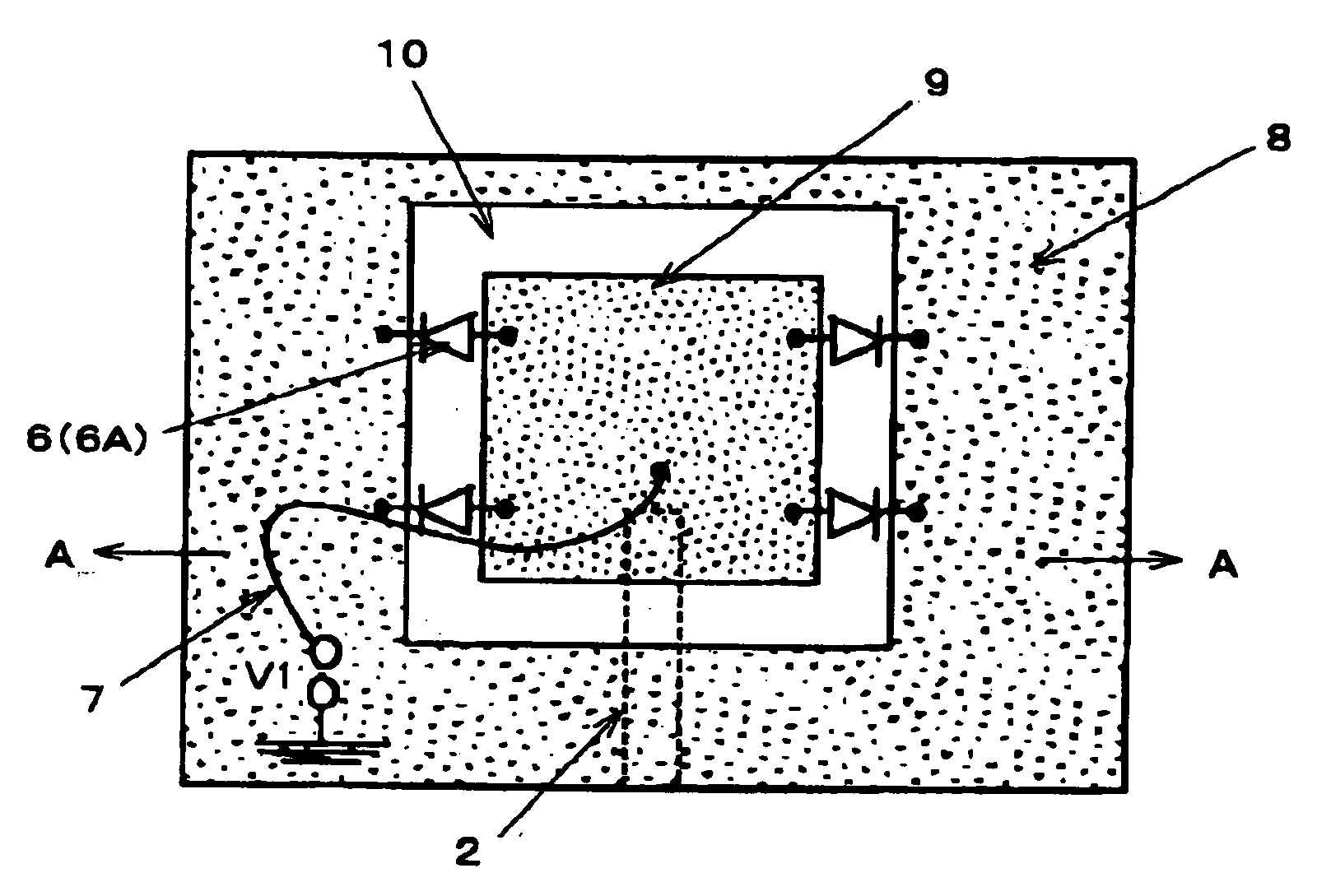
[0028] A frequency-variable slot-line planar antenna according to a first embodiment of the present invention will be described below with reference to FIGS. 3A and 3B. As shown in FIGS. 3A and 3B, the planar antenna according to the first embodiment of the present invention has a slot-line resonator as an antenna radiator which has an electronic device for controlling the electromagnetic wave field of the slot-line resonator.

[0029] The planar antenna has substrate 1 made of a dielectric material and a metal conductor disposed on and extending fully over one principal surface of substrate 1. The metal conductor is partly removed linearly, providing aperture line 10 in the form of a rectangular loop. The portion of the remaining metal conductor which is positioned outside of aperture line 10 is referred to as outer conductor 8, and the portion of the remaining metal conductor which is positioned inside of aperture line 10 is referred to as inner conductor 9. The peripheral edge of o...


PUM


Abstract

A slot-line planar antenna has a substrate, an outer conductor disposed on one principal surface of the substrate and having an opening defined therein, an inner conductor disposed on the one principal surface of the substrate and positioned within the opening, the outer conductor and the inner conductor jointly defining a looped aperture line therebetween, and an electronic device electrically interconnecting the outer conductor and the inner conductor for controlling an electromagnetic wave field of a slot line provided by the aperture line.

Description

BACKGROUND OF THE INVENTION [0001] 1. Field of the Invention [0002] The present invention relates to a planar antenna for use in frequency bands such as millimeter wave and microwave bands, and more particularly to a planar antenna which has a slot line and is capable of controlling an electromagnetic wave field to change an antenna frequency and a plane of polarization and which can be easily designed. [0003] 2. Description of the Related Art [0004] Generally, planar antennas are widely used in radio communications and reception of satellite broadcasts as they can easily be processed and small in size and light in weight. The inventors of the present invention have proposed a planar antenna having an array of slot-line antenna elements disposed on a substrate, as disclosed in Japanese laid-open patent publication No. 2004-7034 (JP, P2004-7034A), and have also proposed a microstrip-line planar antenna for controlling an electromagnetic wave field to change an antenna frequency and a...

Claims


Application Information

Patent Timeline
Patent Type & Authority Applications(United States)
IPC IPC(8): H01Q13/10H01Q13/16
CPCH01Q13/103H01Q9/145
Inventor AIKAWA, MASAYOSHINISHIYAMA, EISUKEASAMURA, FUMIOOITA, TAKEO
Owner NIHON DEMPA KOGYO CO LTD
Why Eureka
Try Eureka