An automatic production equipment for galvanized small-gauge steel wire rope

A production equipment and steel wire rope technology, which is applied in the field of automatic galvanized small-size steel wire rope production equipment, can solve the problems of waste of winding space, difficult operation, and no tension structure for the guide rope structure, and achieve good winding uniformity, The design is reasonable and ingenious, and the effect of improving the winding effect

Active Publication Date: 2021-11-19
南通市一帆钢绳有限公司
View PDF7 Cites 0 Cited by
  • Summary
  • Abstract
  • Description
  • Claims
  • Application Information

AI Technical Summary

Problems solved by technology

[0003] Production equipment often needs auxiliary equipment when producing steel wire ropes. Among them, winding the steel wire rope after production is one of the auxiliary equipment. Nowadays, most winding mechanisms directly wind the steel wire rope on it. With the increase of the number of coils of the steel wire rope increase, often the thickness of the winding position will increase rapidly, while other positions are not well utilized, resulting in a waste of winding space. At the same time, there is no speed reduction mechanism in the auxiliary production equipment. When the winding thickness increases, The winding speed will not be automatically reduced, and it is not easy for subsequent operations. There is no tension structure on the guide rope structure, resulting in poor tension and easy loosening of the guide rope. At the same time, there is no good noise reduction structure in the production equipment. , during production, the noise is concentrated and the noise pollution is serious

Method used


Image

  • An automatic production equipment for galvanized small-gauge steel wire rope
  • An automatic production equipment for galvanized small-gauge steel wire rope
  • An automatic production equipment for galvanized small-gauge steel wire rope

Examples


Embodiment Construction

[0041] The following will clearly and completely describe the technical solutions in the embodiments of the present invention with reference to the accompanying drawings in the embodiments of the present invention. Obviously, the described embodiments are only some, not all, embodiments of the present invention. Based on the embodiments of the present invention, all other embodiments obtained by persons of ordinary skill in the art without creative efforts fall within the protection scope of the present invention.

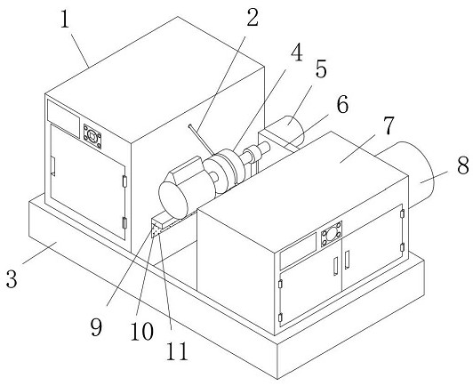
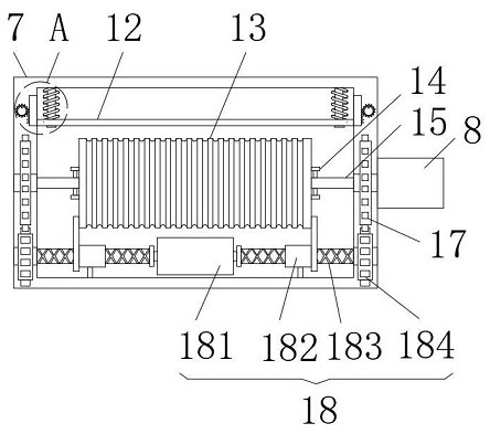
[0042] see Figure 1-9 , the present invention provides a technical solution: an automatic production equipment for galvanized small-size steel wire ropes, comprising a production casing 1, a base 3 and an auxiliary casing 7, the top of the base 3 is fixedly installed with a production casing 1 and an auxiliary The casing 7, the second driving motor 8 is fixedly installed on the side wall of the auxiliary casing 7, and the output shaft end of the second driving mot...


PUM


Abstract

The invention discloses an automatic production equipment for galvanized small-size steel wire ropes, which belongs to the technical field of metal rope manufacturing, and comprises a production casing, a base and an auxiliary casing, and the top of the base is fixedly installed with the production casing and the auxiliary casing; In the present invention, the wire rope produced by the production casing can be quickly rewound by installing the rope take-up roller and the driving machine in the auxiliary casing. At the same time, when the installation main shaft rotates, the driven gear can drive the The driving mechanism rotates. When the driving mechanism rotates, the moving screw sleeve on it can be moved. The side pusher can effectively push the rope take-up roller and move left and right, so that the produced steel wire rope can be effectively and evenly wound on the rope take-up roller. The uniformity of winding is good, and there will be no accumulation of winding in one place, so as to ensure the effective winding. At the same time, the rotating pinch roller can effectively compress the winding steel wire rope to make it more effectively wound. On the take-up roller, improve the take-up effect.

Description

technical field [0001] The invention belongs to the technical field of metal rope manufacturing, in particular to an automatic production equipment for galvanized small-size steel wire ropes. Background technique [0002] Steel wire rope is a kind of metal rope, which is composed of steel wire, rope core and lubricating grease. The steel wire rope is first twisted into strands by multi-layer steel wires, and then twisted into a spiral rope with a certain number of strands around the rope core. Steel wire ropes have a wide range of applications and can be used in various fields with good effects. Steel wire ropes need to use production equipment during production. [0003] Production equipment often needs auxiliary equipment when producing steel wire ropes. Among them, winding the steel wire rope after production is one of the auxiliary equipment. Nowadays, most winding mechanisms directly wind the steel wire rope on it. With the increase of the number of coils of the steel ...

Claims


Application Information

Patent Timeline
Patent Type & Authority Patents(China)
IPC IPC(8): B65H54/40B65H54/70
CPCB65H54/40B65H54/70
Inventor 范本涛
Owner 南通市一帆钢绳有限公司
Why Eureka
Try Eureka