Switch monitoring system, method and equipment

A technology for monitoring systems and switches, applied in the field of switches, can solve problems such as low efficiency in troubleshooting switches, achieve the effect of reducing human resources and time costs, and optimizing work efficiency

Pending Publication Date: 2022-03-01
浪潮思科网络科技有限公司
View PDF0 Cites 0 Cited by
  • Summary
  • Abstract
  • Description
  • Claims
  • Application Information

AI Technical Summary

Problems solved by technology

[0005] The embodiment of the present application provides a switch monitoring system, method and equipment, which are used to solve the problem of low efficiency in troubleshooting switches when there are many switches in the network or the topology is complex

Method used


Image

  • Switch monitoring system, method and equipment
  • Switch monitoring system, method and equipment
  • Switch monitoring system, method and equipment

Examples


Embodiment Construction

[0025] In order to make the purpose, technical solution and advantages of the present application clearer, the technical solution of the present application will be clearly and completely described below in conjunction with specific embodiments and corresponding drawings. Apparently, the described embodiments are only some of the embodiments of the present application, rather than all the embodiments. Based on the embodiments in this application, all other embodiments obtained by persons of ordinary skill in the art without making creative efforts belong to the scope of protection of this application.

[0026] Some embodiments of the present application will be described in detail below with reference to the accompanying drawings.

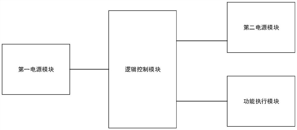
[0027] figure 1 It is a schematic framework diagram of a switch monitoring system provided in the embodiment of the present application.

[0028] Such as figure 1 As shown, the switch monitoring system includes at least a logic control module an...


PUM


Abstract

The invention discloses a switch monitoring system, method and equipment. The monitoring system comprises a logic control module and a first power supply module, the first power supply module is used for supplying power to the logic control module; the logic control module is used for acquiring an interrupt signal of a function execution module in the switch and a voltage value of a second power supply module of the function execution module; monitoring the power supply state of the second power supply module according to the voltage value; and if the power supply state is normal, determining the working state of the function execution module according to the interrupt signal. The interrupt signal of the function execution module in the switch and the voltage value of the second power supply module of the function execution module are obtained through the logic control module, so that the power supply state of the second power supply module and the working state of the function execution module can be automatically monitored, and fault equipment can be timely checked; the complex networking work efficiency and the workload of troubleshooting networking problem points are optimized, and manpower resources and time cost are reduced.

Description

technical field [0001] The present application relates to the technical field of switches, in particular to a switch monitoring system, method and equipment. Background technique [0002] Various types of switches in the network, such as core switches, aggregation switches, and access switches, form a complex network topology. [0003] At present, when the link of a certain network node is not connected, it is often necessary to manually check each switch one by one, first find the faulty switch, and then connect the cable to the computer through the management port of the faulty switch, and initially check the software and hardware faults through instructions , If the fault cannot be solved by software, it is necessary to disassemble the machine and check each functional module of the switch hardware one by one. [0004] The switches in the current network lack intelligent and fast monitoring methods. When there are many switches in the network or the topology is complex, ...

Claims


Application Information

Patent Timeline
Patent Type & Authority Applications(China)
IPC IPC(8): H04L43/0817H04L41/0677
CPCH04L43/0817H04L41/0677
Inventor 徐挺
Owner 浪潮思科网络科技有限公司
Why Eureka
Try Eureka