
Compressor for process during punching and/or riveting

A pressing cylinder, pressing force technology, applied in the field of presses used in processes during stamping and/or riveting, to reduce pressure fluctuations

Pending Publication Date: 2022-04-01
VOITH PATENT GMBH
View PDF17 Cites 0 Cited by
  • Summary
  • Abstract
  • Description
  • Claims
  • Application Information

AI Technical Summary

Problems solved by technology

The spring system generates and limits the pressing force

Method used


Image

  • Compressor for process during punching and/or riveting
  • Compressor for process during punching and/or riveting
  • Compressor for process during punching and/or riveting

Examples


Embodiment Construction

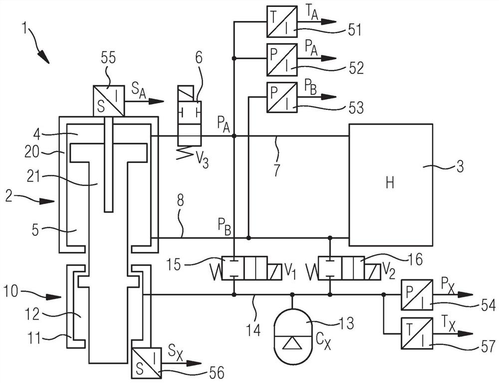
[0037] figure 1 A joining device 1 with a joining drive 2 having a pressing device 10 is shown in FIG. The coupling drive 2 has a differential piston with a piston chamber 4 and an annular chamber 5 . The piston chamber 4 is connected to the hydraulic unit 3 via a supply line 7 . A valve 6 is arranged in the supply line 7 . In the embodiment shown, the reversing valve V is set 3 As valve 6 , the switchover valve can be used to establish and disconnect the connection between hydraulic unit 3 and piston chamber 4 .

[0038] The annular chamber 5 is connected to the hydraulic unit via a supply line 8 . No valve is provided in this supply line 8 . To detect the position of the piston, a position sensor 55 is provided. The pressure P provided by the hydraulic circuit is detected via the pressure sensor 52 A . The temperature of the hydraulic medium T A Received by temperature sensor 51. To detect the pressure P in the supply line 8 to the annular chamber 5 B , a pressure...


PUM


Abstract

The invention relates to a presser for an engagement drive and an engagement drive having a presser. The presser comprises a pressing cylinder, and the pressing cylinder provides pressing force by applying pressure to the pressure cavity. Preferably, the pressure chamber is formed by a pressing cylinder and a punch which engages the drive. The pressure loading required to provide the pressing force is provided by means of a hydraulic circuit which engages the drive. In the engagement operation, the pressure chamber of the presser is connected to the pressure accumulator of the presser, such that there is no significant influence on the pressure in the pressure chamber by a change in the volume of the pressure chamber of the presser.

Description

technical field Background technique [0001] The riveting process or riveting described in Wikipedia under riveting process is a production method belonging to the group of joints by reforming, which includes the production of riveted connections. During riveting, the auxiliary joint, ie the rivet(s), is plastically deformed at the connection hole. Riveting is a joining method used especially for sheet metal and similar low-strength semi-finished products. [0002] The purpose of punch riveting is the indirect, non-detachable joining of sheet metal parts without the need for pre-cut holes as in the case of conventional solid or blind rivets. Rivet elements (auxiliary joints) are used for this purpose, which at the same time serve as punches. Depending on the rivet elements used, in principle two punch riveting methods are relevant: punch riveting with solid rivets or punch riveting with semi-tubular rivets. What these two methods have in common is that they require that th...

Claims


Application Information

Patent Timeline
Patent Type & Authority Applications(China)
IPC IPC(8): B21J15/02B21J15/06B21J15/20B21J15/28
CPCB21J15/025B21J15/20B21J15/28B21D39/031B21D39/03
Inventor 伯特·布拉梅尔
Owner VOITH PATENT GMBH
Learn More