Garbage incinerator

A garbage incinerator and shell technology, which is applied in the field of incineration, can solve the problems of garbage dispersal and other problems, and achieve the effects of preventing garbage from smoldering, improving practicability, and evenly distributing garbage

Inactive Publication Date: 2022-04-29
王硕
View PDF1 Cites 0 Cited by
  • Summary
  • Abstract
  • Description
  • Claims
  • Application Information

AI Technical Summary

Problems solved by technology

[0006] Aiming at the deficiencies of the prior art, the present invention provides a garbage incinerator, which solves the problem that the device cannot push and disperse the accumulated garbage when incinerating the garbage, effectively prevents the garbage from smoldering, and realizes that the pushing plate The purpose of falling the garbage on the top is to make the garbage in the incineration chamber more evenly distributed, to facilitate the continuous turning of the garbage in the incineration chamber, so that the garbage in the incineration chamber can fully contact with the air, and achieve the purpose of more complete combustion. Reduce the generation and emission of harmful gases

Method used


Image

  • Garbage incinerator
  • Garbage incinerator
  • Garbage incinerator

Examples


Embodiment 1

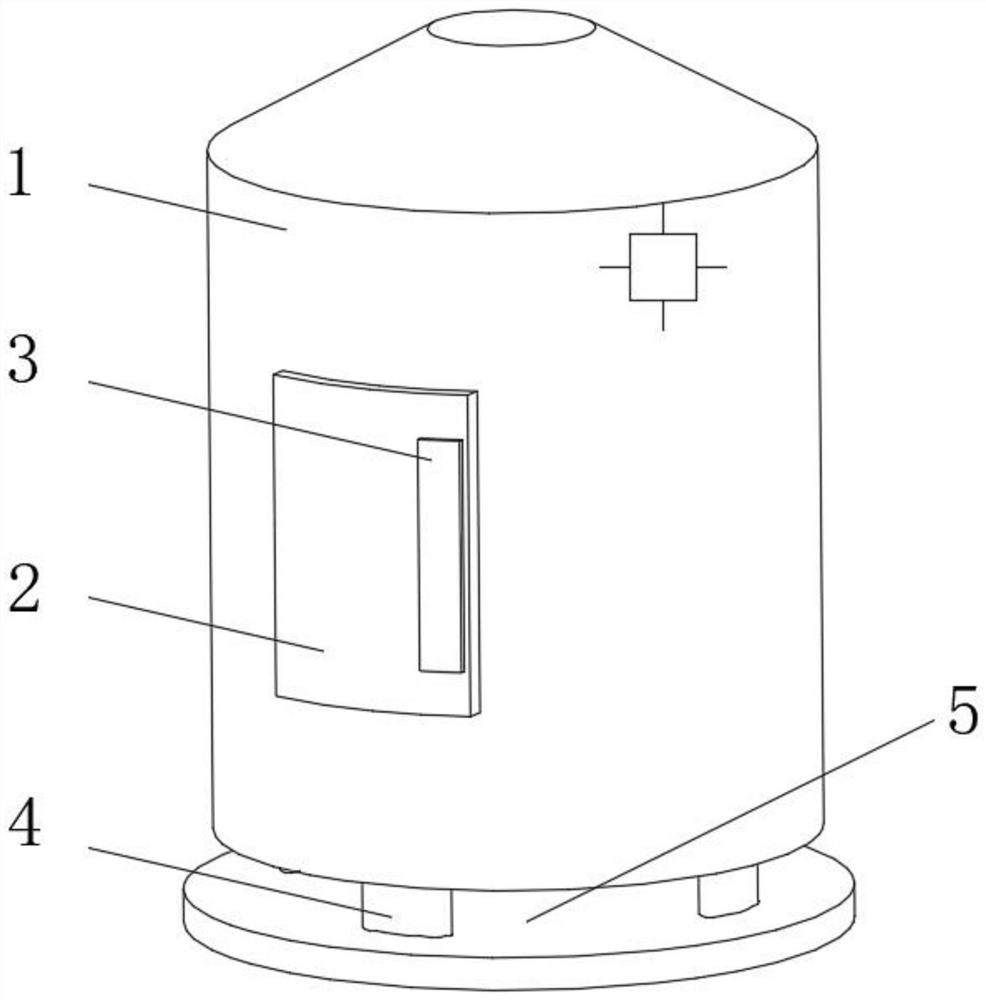
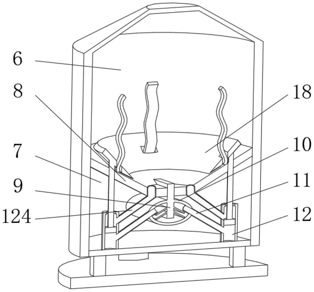
[0028] see Figure 1-4 , the present invention provides a technical solution: a garbage incinerator, comprising a shell (1), characterized in that: a feed door (2) is installed on one side of the shell (1), and the feed door (2 ) is equipped with a heat-insulating handle (3), the bottom of the housing (1) is evenly equipped with a support frame (4), and the end of the support frame (4) away from the housing (1) is fixedly connected with a base (5 ), the inside of the shell (1) is provided with an incineration chamber (6) and a control chamber (7), and the incineration chamber (6) and the control chamber (7) are separated by a conical partition (8), so One side of the tapered partition (8) is fixedly connected with a heat conduction plate (9), and the inside of the control chamber (7) is equipped with a reaction frame (10) near the position of the tapered partition (8). One side of the plate (9) extends through the tapered partition (8) to the inside of the reaction frame (10)...

Embodiment 2

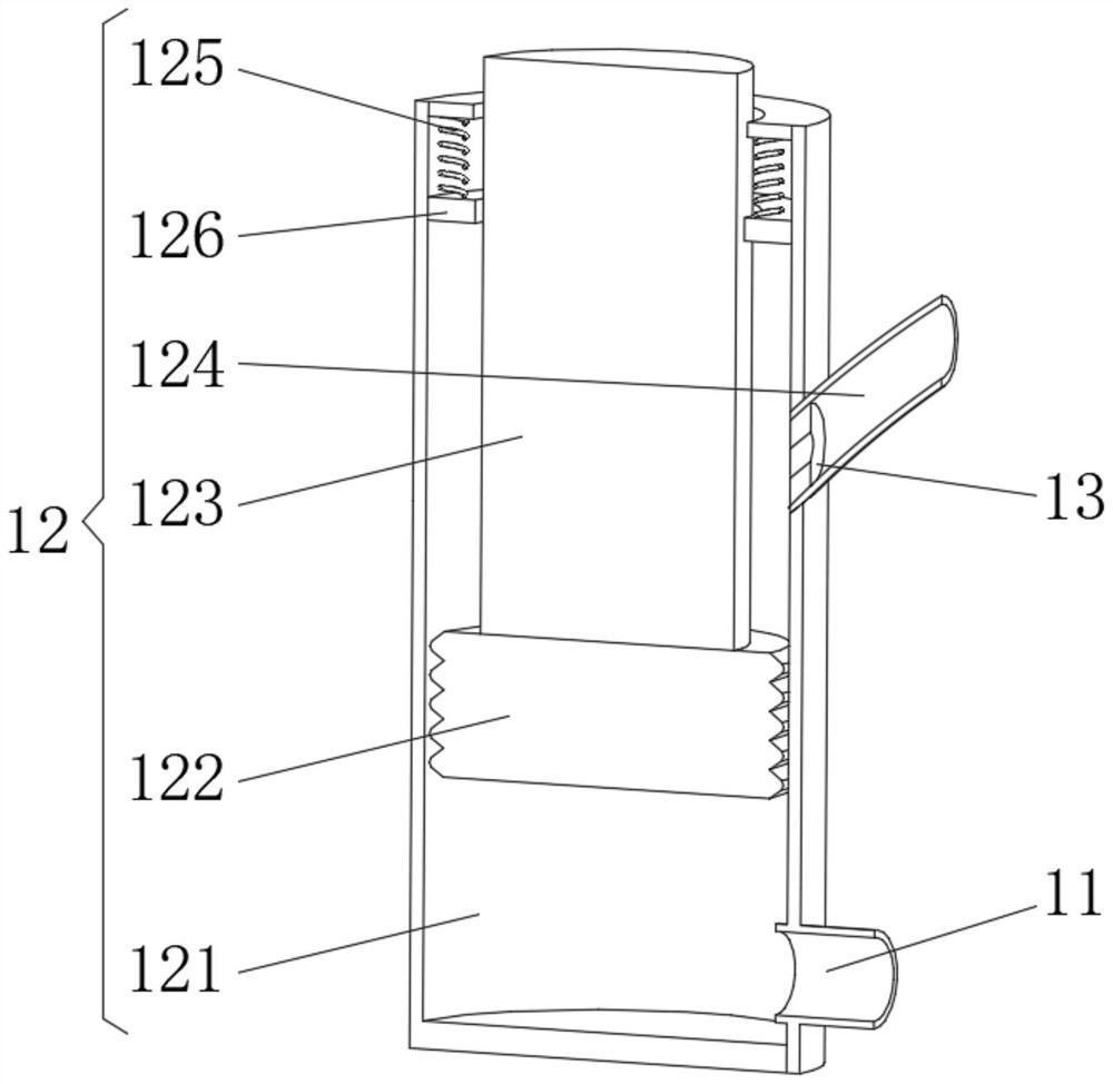
[0034] see Figure 1-5 , the present invention provides a technical solution: on the basis of Embodiment 1, a hole adjustment device (13) is installed inside the pushing device (12), and the hole adjustment device (13) includes a fixing plate (131), the The outer side of the fixed plate (131) is rotatably connected with the inner wall of the air outlet pipe (124), and one side of the fixed plate (131) is provided with an annular groove (132), and the inner wall of the annular groove (132) is fixedly connected with an extrusion Spring (133), one end of described extruding spring (133) is fixedly connected with movable fan-shaped plate (134), and the side of described movable fan-shaped plate (134) away from extruding spring (133) runs through and is connected with guide plate ( 135), the end of the guide plate (135) away from the movable fan-shaped plate (134) is fixedly connected with an air pipe (136).

[0035] The outer sides of the ventilation pipe (136) are provided with ...


PUM


Abstract

The garbage incinerator comprises a shell, a feeding door is installed on one side of the shell, a heat insulation handle is installed on one side of the feeding door, supporting frames are evenly installed at the bottom of the shell, the ends, away from the shell, of the supporting frames are fixedly connected with a base, and an incineration cavity and a control cavity are formed in the shell; the incineration cavity and the control cavity are separated through a conical partition plate, a heat conduction plate is fixedly connected to one side of the conical partition plate, a reaction frame is installed at the position, close to the conical partition plate, in the control cavity, one side of the heat conduction plate penetrates through the conical partition plate and extends into the reaction frame, and gas conveying pipes symmetrically communicate with the interior of the reaction frame. And the end, away from the reaction frame, of the gas conveying pipe communicates with a pushing device. According to the garbage incinerator, the purpose of pushing accumulated garbage to be scattered is achieved, and garbage smoldering is effectively prevented.

Description

technical field [0001] The invention relates to the technical field of incineration, in particular to a garbage incinerator. Background technique [0002] The amount of municipal solid waste generated doubles every year. The traditional way of garbage disposal is to build a landfill to bury the garbage. There are many disadvantages in this method, such as taking up a lot of land to build a landfill, and the toxic filtrate produced after a large amount of organic matter and batteries are buried will bring serious pollution to the soil and groundwater. Compared with landfill treatment, using Incineration of garbage is a better treatment method. [0003] For example, Chinese patent CN106610020A proposes a garbage incinerator, which includes a feed structure and a furnace body. One side is provided with a drive shaft, the drive shaft is provided with an arc-shaped tooth block matching the gear, the drive shaft is provided with a chute and a slide block slidably connected with...

Claims


Application Information

Patent Timeline
Patent Type & Authority Applications(China)
IPC IPC(8): F23G5/28F23G5/44F23L7/00
CPCF23G5/28F23G5/44F23L7/007
Inventor 王硕
Owner 王硕
Why Eureka
Try Eureka