Design method and device for novel roof additional component of transformer substation prefabricated cabin

A design method and prefabricated cabin technology, applied in the field of construction, can solve the problems of unsightly and unrealistic building appearance, achieve the effects of improving wind resistance safety, simple structure, and reducing extreme negative pressure

Pending Publication Date: 2022-05-27
GUANGDONG POWER GRID CO LTD +1
View PDF0 Cites 0 Cited by
  • Summary
  • Abstract
  • Description
  • Claims
  • Application Information

AI Technical Summary

Problems solved by technology

For industrial buildings such as prefabricated cabin substations, it is unrealistic to modify the design of the eaves and set up a parapet on the roof ridge, and the building appearance is not beautiful enough

Method used


Image

  • Design method and device for novel roof additional component of transformer substation prefabricated cabin
  • Design method and device for novel roof additional component of transformer substation prefabricated cabin
  • Design method and device for novel roof additional component of transformer substation prefabricated cabin

Examples


Embodiment 1

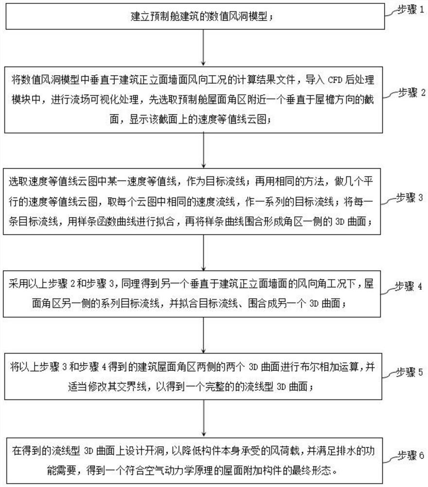
[0049] see figure 2 As shown, this embodiment provides a design method for a new type of roof additional component for a prefabricated cabin of a substation, including:

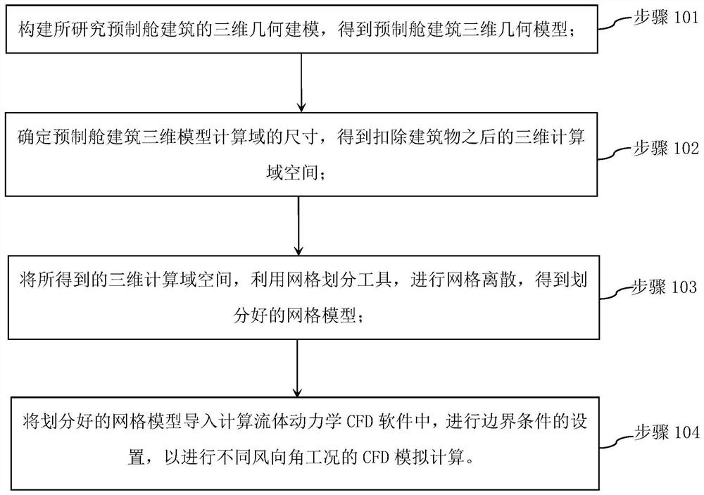
[0050] Step 1: Based on the principle of Computational Fluid Dynamics (CFD), establish the numerical wind tunnel model of the prefabricated cabin building;

[0051] Step 2: Import the calculation result file of the numerical wind tunnel model perpendicular to the wind direction of the building's front facade into the CFD post-processing module, and perform flow field visualization processing. A section of the direction, showing the velocity contour contour map on the section;

[0052]Step 3: Select a certain velocity contour in the velocity contour cloud as the target streamline; then use the same method to make several parallel velocity contour contours, and take the same velocity streamline in each cloud, Make a series of target streamlines; fit each target streamline with a spline function curve, and th...

Embodiment 2

[0072] This example takes a prefabricated cabin integrated cabin building of a substation as an example. The 3D model of the building is as follows Figure 4 shown. The specific embodiments and steps of the aerodynamic components designed by the present invention are as follows:

[0073] (1) According to the designed original cabin building design scheme, establish the corresponding numerical wind tunnel model, such as Figure 5 , Image 6 As shown, the simulation calculation of the flow field around it under the action of strong wind is carried out.

[0074] (2) Based on the distribution of the flow field around the prefabricated cabin obtained by numerical simulation, make a wind speed cloud map on a certain section, such as Figure 7 shown. Take a certain wind speed streamline in the wind speed cloud map as the target curve, and use spline curve to fit.

[0075] (3) Make a series of streamline curves (4 here) on the edge of the eaves in the corner area of ​​the roof of...

Embodiment 3

[0080] see Figure 13 As shown in the figure, the design device for a new type of roof additional component for a prefabricated cabin of a substation provided in this embodiment includes a processor, a memory, and a computer program stored in the memory and running on the processor, for example, optimizing the corner area of ​​the roof of the prefabricated cabin of the substation Additional member design program for wind loads. When the processor executes the computer program, the steps of Embodiment 1 above are implemented, for example figure 2 steps shown.

[0081] Exemplarily, the computer program may be divided into one or more modules / units, and the one or more modules / units are stored in the memory and executed by the processor to accomplish the present invention. The one or more modules / units may be a series of computer program instruction segments capable of accomplishing specific functions, and the instruction segments are used to describe the execution process of ...


PUM


Abstract

The invention discloses a design method and device for a novel roof additional component of a prefabricated cabin of a transformer substation, and the outline of an aerodynamic component is obtained by means of computational fluid dynamics numerical simulation of a flow field around the prefabricated cabin transformer substation. After the aerodynamic component is mounted on the original structure, the local aerodynamic shape is scientifically changed, so that the flow field of the corner area of the prefabricated cabin is attached to the profile of the component, and flow separation and vortex generation in the corner area of the prefabricated cabin are inhibited. Compared with the situation that no component exists or a simple permeable parapet wall structure is adopted in previous research, vortex and separated flow in a structure corner area can be scientifically restrained, so that extreme value negative pressure is reduced, the wind resistance safety of the structure is improved, and the structure is simple and attractive while the function is met.

Description

technical field [0001] The invention relates to the field of construction, in particular to a design method and device for a new type of roof additional component for a prefabricated cabin of a substation. Background technique [0002] In the southeastern coastal areas of my country, low-rise buildings represented by double-slope roofs are widely used in some occasions. Under the action of strong winds, such buildings are also prone to wind damage and damage, and their wind resistance cannot be ignored. The results of the on-site investigation of the wind disaster show that the damage of the low double-slope roof building under the wind disaster is mainly the damage of the enclosure structure, which is mainly manifested as the damage of the vulnerable parts such as the corner of the windward roof, the edge of the eaves and the ridge, or the overall and local damage of the roof. This led to the collapse of the building as a whole. [0003] The damage mechanism of low buildin...

Claims


Application Information

Patent Timeline
Patent Type & Authority Applications(China)
IPC IPC(8): G06F30/13G06F30/23G06F30/28G06T17/20G06F113/04G06F113/08G06F113/10G06F119/14
CPCG06F30/13G06F30/28G06F30/23G06T17/205G06F2113/10G06F2113/04G06F2113/08G06F2119/14Y02B10/30
Inventor 雷翔胜周继承王流火王彦峰王兴华钟伟华廖一键杨易张之远
Owner GUANGDONG POWER GRID CO LTD
Why Eureka
Try Eureka