Support structure for safety helmet

A technology for safety helmets and shields, which is applied to headgear products, clothing, helmets, etc., can solve the problem that the wearer cannot provide safety guarantee, the wearer cannot provide a good wearing feeling, and the thickness of the cap body and the buffer pad changes. big problem

Inactive Publication Date: 2005-08-10
ARAI HELMET LTD
View PDF1 Cites 0 Cited by
  • Summary
  • Abstract
  • Description
  • Claims
  • Application Information

AI Technical Summary

Problems solved by technology

[0009] However, if this structure is used, the thickness of the buffer pad used to absorb the impact on the wearer's head must be reduced according to the degree of inward protruding of the cap body, so that safety cannot be provided for the wearer.
[0010] In terms of ensuring the thickness of the cushion pad, although the thickness

Method used


Image

  • Support structure for safety helmet
  • Support structure for safety helmet
  • Support structure for safety helmet

Examples


Embodiment Construction

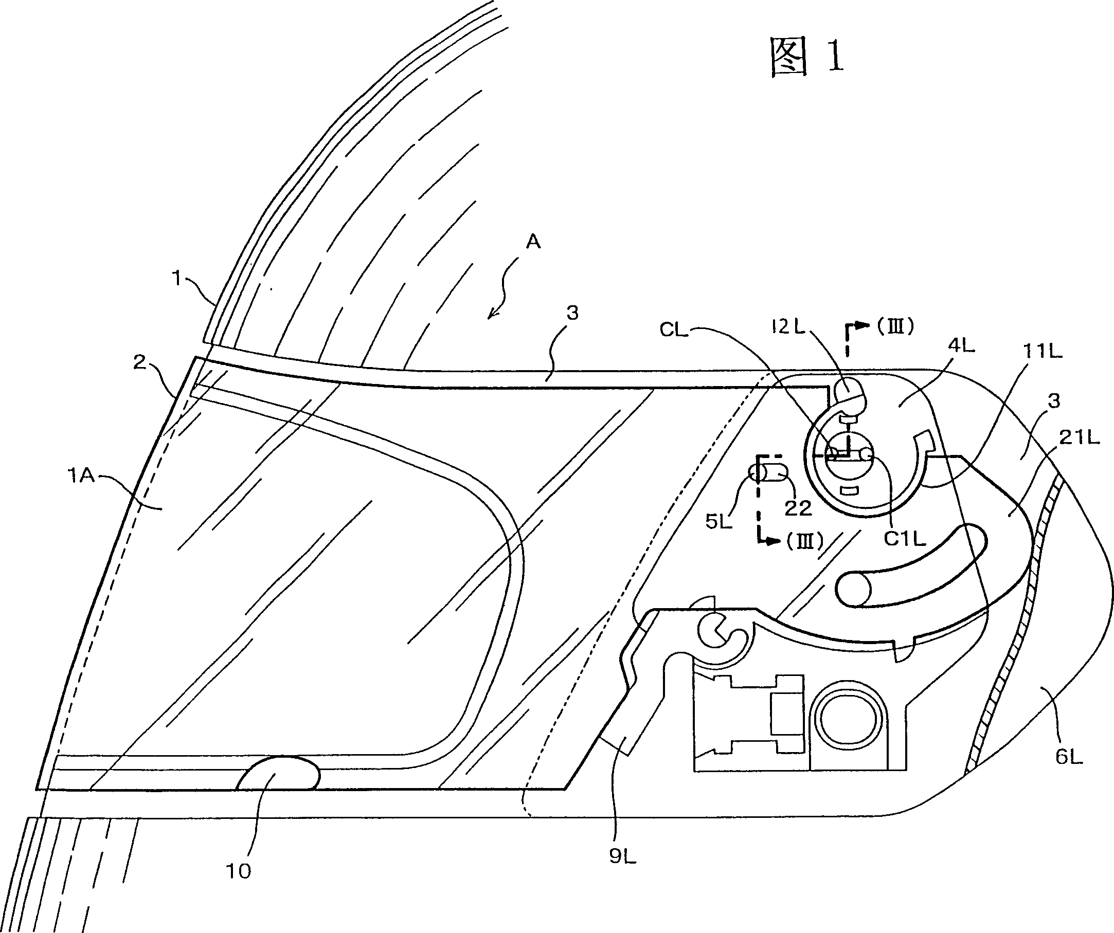
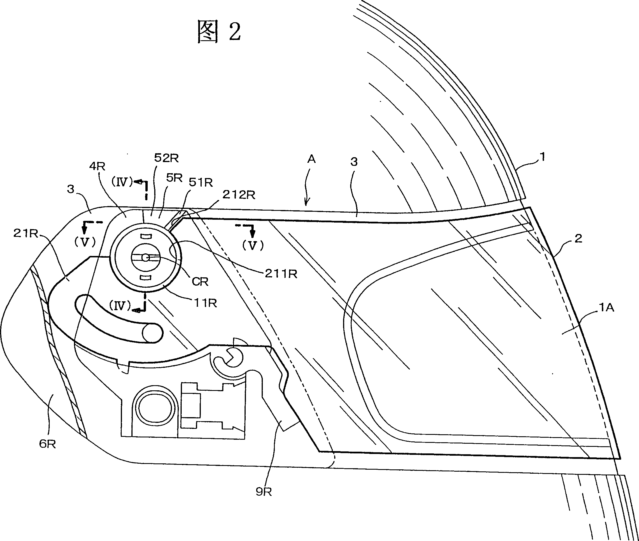
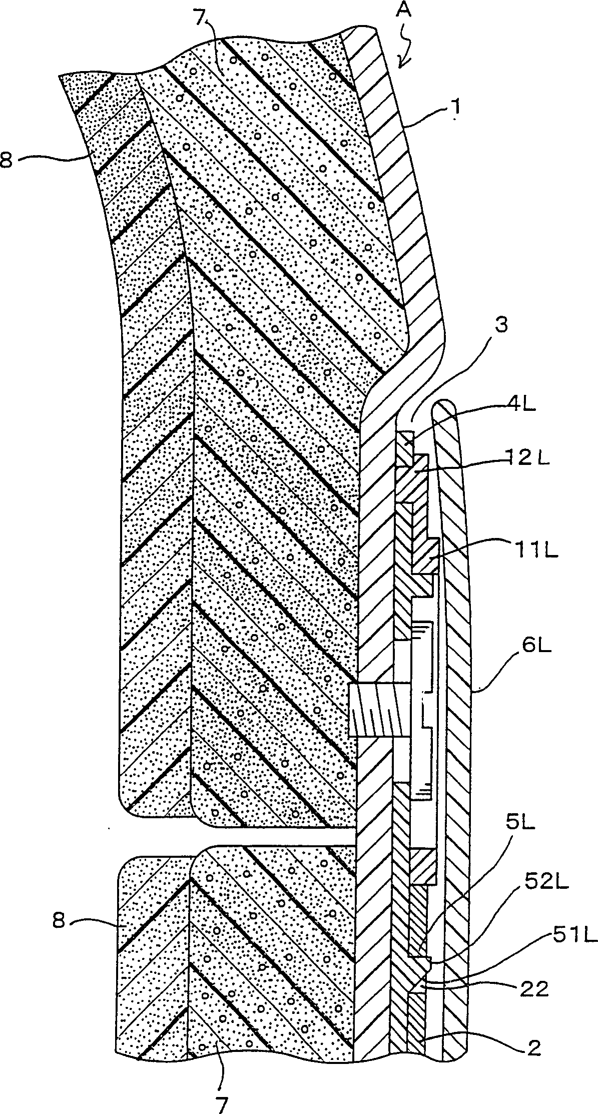
[0040] The technical means adopted by the shield support structure of the safety helmet of the present invention is to form a step portion 3 at least to accommodate the shield 2 on the shield installation position of the cap body 1. When the shield is fully closed, its appearance forms a shield. The outer surface of the cover 2 is substantially on the same plane as the outer surface of the cap body 1, and the shield mounting parts 21L, 21R of the supporting shafts 11L, 11R on the left and right sides of the cap body 1 can be arranged on the base element of the cap body 1. The pivot centers CL and CR on 4L and 4R are rotated around the center to open and close the shield 2. It is characterized in that when the shield 2 is fully closed, the axis C1L of one side support shaft (11L in the figure) It is the state behind the above-mentioned rotation axis center CL. When the shield 2 is moved forward in this state, and the axis C1L of the support shaft 11L advances to a position conce...


PUM


Abstract

The invention provides a new supporting structure for a shield having effects on the security of shock absorbing properties and aerodynamic characteristics and good comfortableness to wear, further suppression of a wind noise with a traveling wind and prevention of falling off of the shield due to a step part thereof caught with a road surface, or the like even if overturn is caused. The solution method of the invetion is that, the outer surface of the shield 2 is nearly flush with the outer surface of the hat body 1 when the shield 2 is fully closed, and characterised in that making the shield 2 emerge and sink in the step part 3 by lifting and lowering the shield 2 relatively to slope parts 5L and 5R when the shield 2 is moved back and forth according to the forward and backward movement of a supporting shaft 11L, and the shield 2 is vertically rotated.

Description

technical field [0001] The present invention relates to the installation structure of the protective cover installed on the full-face type and spray type helmets for protecting the head and face when riding various vehicles such as motorcycles and four-wheeled vehicles or mobile machines. It is an improvement of the guard installation structure in which the outer surface of the guard and the outer surface of the cap are approximately on the same plane when the guard is fully closed. Background technique [0002] According to the known technology of the present invention, at least a step portion for accommodating the shield is formed at the shield installation position of the cap body. The shroud supporting structure on the same surface is disclosed in, for example, Japanese Patent Application Laid-Open No. 2-22329. [0003] The creation disclosed in this gazette is that when the shield is fully closed, the shield and the step difference portion (referred to as the section i...

Claims


Application Information

Patent Timeline
IPC IPC(8): A42B3/24A42B3/18
Inventor 新井理夫
Owner ARAI HELMET LTD
Why Eureka
Try Eureka