Vehicle bumper beam and manufacturing method thereof

A technology for bumpers and beams, applied to bumpers and other directions, can solve problems such as shear damage, improve impact absorption characteristics, realize miniaturization, and achieve lightweight effects

Inactive Publication Date: 2014-10-15
RESONAC HOLDINGS CORPORATION
View PDF10 Cites 2 Cited by
  • Summary
  • Abstract
  • Description
  • Claims
  • Application Information

AI Technical Summary

Problems solved by technology

Where the bumper reinforcement and crush box are bolted in place, there is a risk of accidental shear failure in the event of a crash

Method used


Image

  • Vehicle bumper beam and manufacturing method thereof
  • Vehicle bumper beam and manufacturing method thereof
  • Vehicle bumper beam and manufacturing method thereof

Examples


no. 1 approach

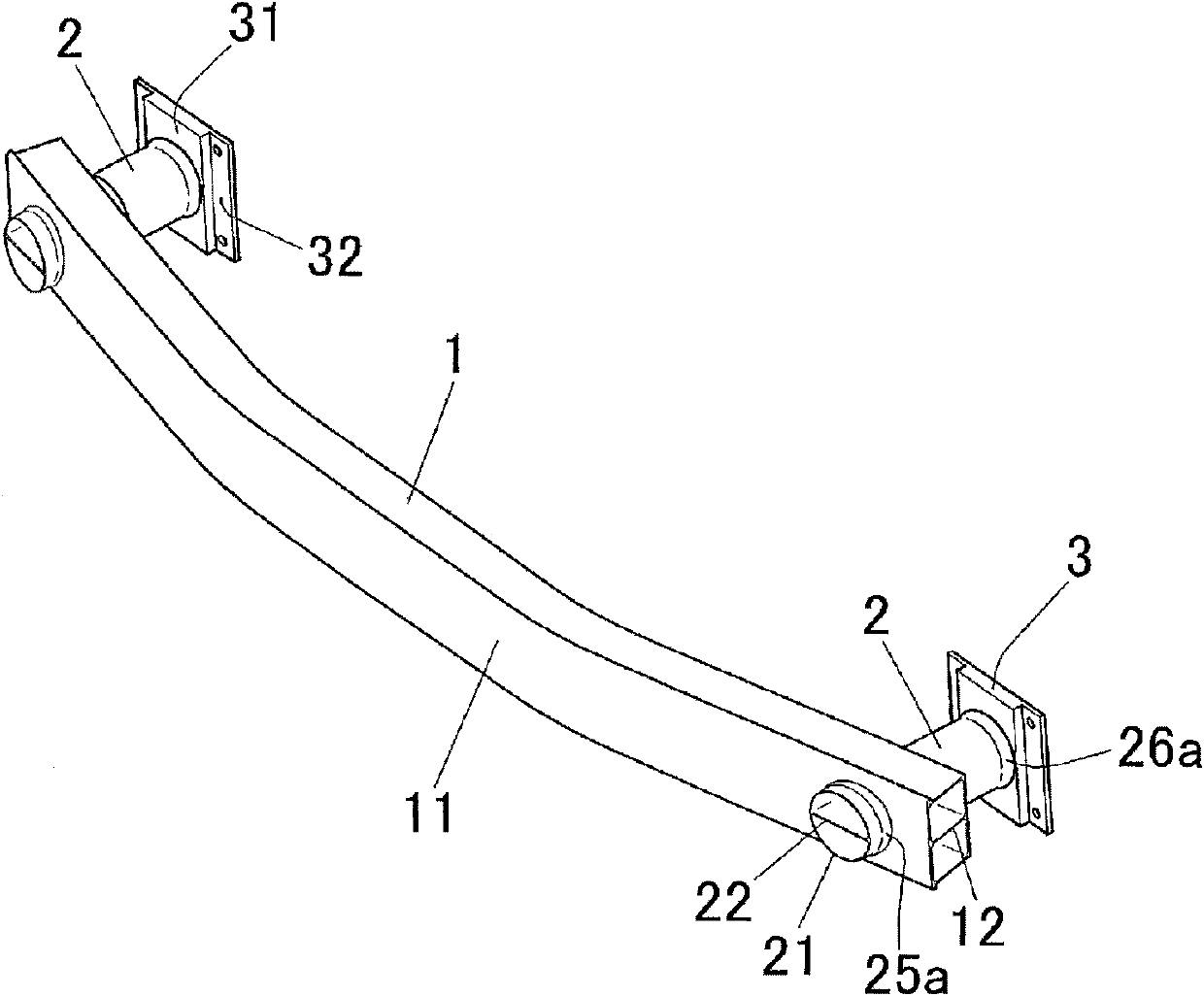
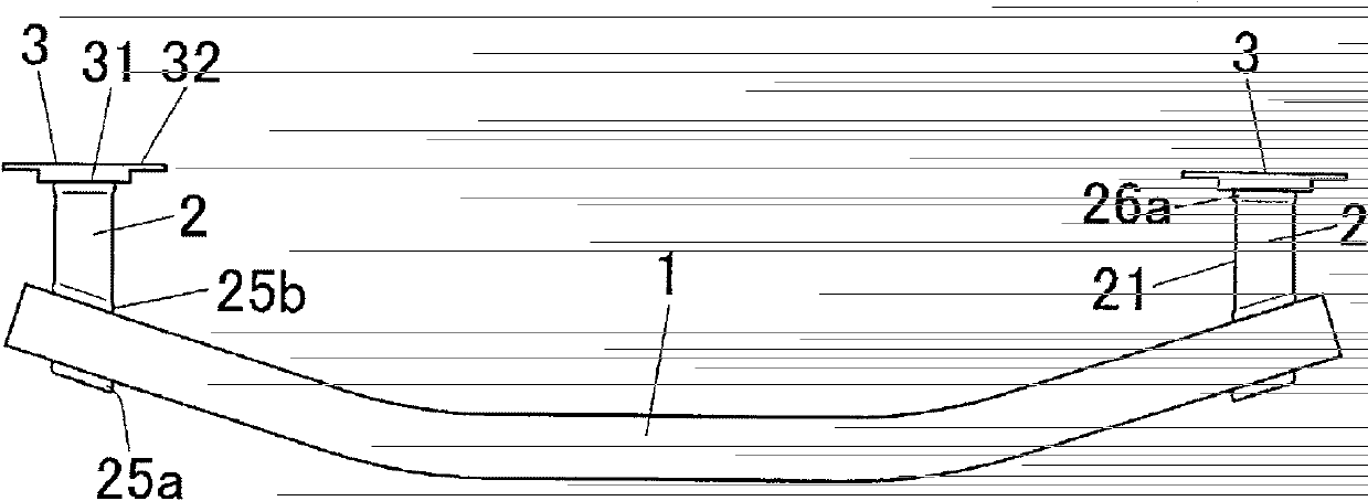
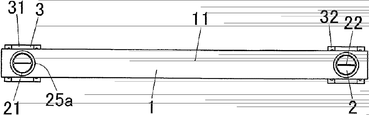
[0070] figure 1 It is a perspective view showing a vehicle bumper beam according to a first embodiment of the present invention. figure 2 It is a plan view showing the vehicle bumper beam according to the first embodiment. image 3 It is a front view showing the vehicle bumper beam according to the first embodiment. Figure 4 It is a side view showing the vehicle bumper beam according to the first embodiment. Figure 5 It is a horizontal sectional view showing the vehicle bumper beam according to the first embodiment. Figure 6 It is an enlarged perspective view showing a side portion of the vehicle bumper beam according to the first embodiment. Figure 7 It is an enlarged horizontal cross-sectional view showing a side portion of the vehicle bumper beam according to the first embodiment.

[0071] As shown in these figures, the bumper beam is provided at the front end of the vehicle for impact absorption at the time of collision. The bumper beam includes: a bumper reinfor...

no. 2 approach

[0107] Figure 9 It is a perspective view showing a vehicle bumper beam according to a second embodiment of the present invention. Figure 10 It is an enlarged perspective view showing a side portion of the vehicle bumper beam according to the second embodiment. Figure 11 It is an enlarged horizontal cross-sectional view showing a side portion of the vehicle bumper beam according to the second embodiment.

[0108] As shown in these figures, in this bumper beam, at an intermediate position in the longitudinal direction (axial direction) of the crush can 2, a single protrusion 27 for a starting point of deformation is formed continuously in the circumferential direction by pipe expansion processing. .


PUM


Abstract

The bumper beam of the present invention includes a hollow tubular bumper reinforcement (1) and a hollow tubular crush box (2). A reinforcement hole (15) is formed to penetrate through an outer peripheral wall (11) of a bumper reinforcement (1). A partition wall (22) is provided in a bridging manner between opposing inner wall surfaces of the outer peripheral wall (21) of the crush can (2). The top end of the crush can (2) passes through the reinforcement hole (14). In this state, protrusions (25a), (25b) are formed in the circumferential direction on the front and rear sides of the reinforcement hole (15) of the crush can (2) by pipe expansion using a pipe expansion die. . In this way, the crush can (2) is fixed to the bumper reinforcement (1). According to the present invention, the size and weight of the bumper beam can be reduced.

Description

technical field [0001] The present invention relates to, for example, a vehicle bumper beam provided at the front end and / or rear end of an automobile and a method of manufacturing the same. Background technique [0002] Set the bumper on the front end of the car. On the inside of the bumper, a bumper beam is provided to absorb the impact of a collision. [0003] The bumper beam generally includes a bumper reinforcement arranged in the vehicle width direction at the front of the vehicle, and a pair of left and right crush boxes that support the bumper reinforcement on the vehicle structure. The bumper beam absorbs crash energy by deforming itself. Damage to vehicle components other than the bumper beam is suppressed by absorbing the impact energy. [0004] In this type of bumper beam, the fixation of the bumper reinforcement and the crush box is mainly welded or bolted. In the case where the bumper reinforcement and the crush box are fixed by welding, the cost may increa...

Claims


Application Information

Patent Timeline
Patent Type & Authority Patents(China)
IPC IPC(8): B60R19/24B60R19/34
CPCY10T29/49938B60R19/34Y10T29/49622B21D39/044
Inventor 小久保贞男川又保二山口聪
Owner RESONAC HOLDINGS CORPORATION
Why Eureka
Try Eureka