Dynamic light coupler

An optical coupler and dynamic technology, applied in the field of optical communication, can solve the problems of no dynamic optical coupling structure, limited application range, inability to realize beam splitting and beam combining conversion, etc., and achieve the effect of easy operation

Inactive Publication Date: 2006-02-22
SHANGHAI INST OF OPTICS & FINE MECHANICS CHINESE ACAD OF SCI
View PDF1 Cites 1 Cited by
  • Summary
  • Abstract
  • Description
  • Claims
  • Application Information

AI Technical Summary

Problems solved by technology

Prior art [1] (J.J.Pan and T.Zhu, "1×N fiber coupler employing diffractive optical element", Electronics Letters 35, No.4, 324-325 (1999)) once proposed to realize 1×N fiber coupler using diffractive optical element Optical fiber coupling structure, but no dynamic optical coupling structure is proposed, that is, this structure can only realize light splitting, but not light combining, nor can it realize the conversion between splitting and combining beams
Prior Art [2] (Zhou Changhe, Zhao Xin, Liu Liren, "Dynamic Coupler Used in Optical Communication", Application Date: October 22, 2001, Application Number: 01131972.0, Publication Number: CN1343894A, Publication Date: 2002 On April 10, 2009, applicant country: China) proposed a dynamic optical coupler based on an even-numbered Damman grating, which can realize dynamic beam splitting and beam combining, which greatly promotes the intersection of binary optics and optical fiber communication. application, but the movement of the displacement device requires high precision (micron level), and is limited to an even number of equal-intensity spot outputs, and the application range is limited

Method used


Image

  • Dynamic light coupler
  • Dynamic light coupler
  • Dynamic light coupler

Examples


Embodiment Construction

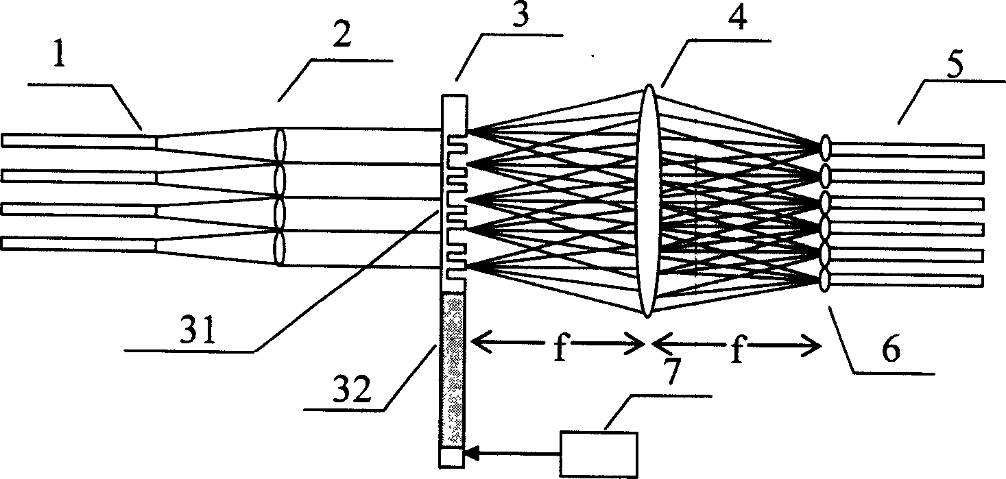
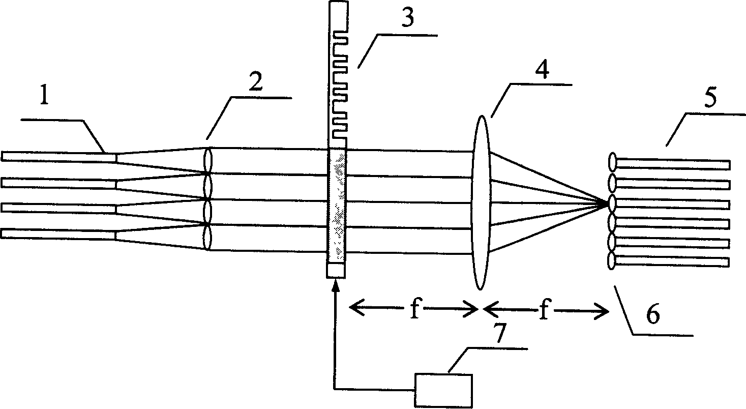
[0040] see first figure 1 , figure 1 It is a specific embodiment of the present invention, as can be seen from the figure, the composition of the dynamic optical coupler of the present invention: on an optical path, input fiber group 1, collimating lens group 2, Damman grating phase plate 3, converging lens 4 are successively and output fiber group 5. Wherein the input fiber group 1 is placed on the front focal plane of the collimating lens 2, the phase plate 3 is placed on the back focal plane of the collimating lens group 2, which is also the front focal plane of the converging lens 4, and the output fiber group 5 is placed on the converging On the rear focal plane of the lens 4, the number of fibers of the two fiber groups may be the same or different, denoted as N and M. The output fiber group 5 has an autocollimating lens 6 . The phase plate 3 has a shifter 7 . The numerical aperture of the converging lens 4 matches that of the autocollimating lens.

[0041] The Damm...


PUM


Abstract

A dynamic light coupler consists of input optical fibre set, collimation lens set, Daman grating phase plate, convergent lens and output optical fibre set in sequence on one light path. It is featured as setting input optical fibre set on front focal plane of collimation lens, phase plate at back focal plane, output optical fibre set on back focal plane of convergent lens; overlapping convergent lens front focal plane to back focal plane of collimation lens set.

Description

technical field [0001] The present invention relates to optical communication, in particular to a dynamic optical coupler which utilizes a diffractive optical element Damman grating to realize a large number of dynamic optical coupling and optical beam splitting. Background technique [0002] With the development of science and technology and society, people's demand for information is gradually increasing. With its advantages of high speed, large capacity, good confidentiality and low cost, optical fiber communication surpasses traditional cable communication and is the development direction of communication technology in the 21st century. How to realize the dynamic optical coupling technology from N-channel to M-channel and N-channel to single-channel has become a key issue to accelerate the development of optical communication technology. [0003] At present, the beam splitting in optical communication mostly uses conventional fused-taper fiber couplers, which are charac...

Claims


Application Information

Patent Timeline
Patent Type & Authority Patents(China)
IPC IPC(8): G02B6/26
Inventor 周常河底彩慧
Owner SHANGHAI INST OF OPTICS & FINE MECHANICS CHINESE ACAD OF SCI
Why Eureka
Try Eureka