Optical Beam Splitter Based on Aperiodic Subwavelength Grating and Its Design Method

A sub-wavelength grating and optical beam splitter technology, applied in the field of optoelectronics, can solve the problems of unable to maintain the overall shape of the incident light, split the incident light spot, etc., and achieve the effects of low energy loss, high fabrication tolerance, and simple grating structure

Active Publication Date: 2020-06-16
BEIJING UNIV OF POSTS & TELECOMM
View PDF5 Cites 0 Cited by
  • Summary
  • Abstract
  • Description
  • Claims
  • Application Information

AI Technical Summary

Problems solved by technology

[0004] Classical optical beam splitters use semi-transparent mirrors to split transmitted light and reflected light; waveguide beam splitters use planar waveguides to split beams on a plane; beam splitters based on subwavelength gratings can split light in the vertical direction. Beam splitting, but generally sub-wavelength grating beam splitters use deflection gratings to deflect two parts of light in two directions, which cannot maintain the overall shape of the incident light. Although power splitting can be achieved, it will split the shape of the incident spot

Method used


Image

  • Optical Beam Splitter Based on Aperiodic Subwavelength Grating and Its Design Method
  • Optical Beam Splitter Based on Aperiodic Subwavelength Grating and Its Design Method
  • Optical Beam Splitter Based on Aperiodic Subwavelength Grating and Its Design Method

Examples


Embodiment Construction

[0031] The structures and technical solutions in the embodiments will be fully and clearly described below in conjunction with the embodiments of the present invention and the accompanying drawings. This embodiment is only a part of the embodiments of the present invention, but not all of them. All other embodiments obtained by persons of ordinary skill in the art on the basis of the embodiments of the present invention without making creative efforts belong to the protection scope of the present invention.

[0032] The present invention firstly provides a method for designing an optical beam splitter based on an aperiodic subwavelength grating, which specifically includes steps:

[0033] Step 1: Establish a three-dimensional coordinate system.

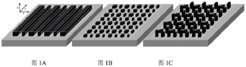
[0034] see Figure 1A ~ Figure 1C , according to the dimensions of the grating to be designed, a three-dimensional coordinate system oxyz is established on the planar dielectric base, where the x-axis and y-axis are located in the p...


PUM

PropertyMeasurementUnit
thicknessaaaaaaaaaa
transmittivityaaaaaaaaaa

Abstract

The invention, which belongs to the technical field of optoelectronics, discloses an optical beam splitter based on a non-periodic sub-wavelength grating and a design method thereof. The method comprises: establishing a three-dimensional coordinate system; forming a non-periodic grating basic unit by one-dimensional, two-dimensional and three-dimensional gratings; and extending the grating basic unit periodically to form an optical beam splitter having two deflection angles. Therefore, the light beam splitting in a vertical direction is realized; only power beam splitting is carried out; and the sub beam-splitting light can be kept in an incident light state. The grating basic unit formed based on the grating block structure is arranged periodically to form any one-dimensional, two-dimensional and three-dimensional grating; and the infinite extension is realized.

Description

technical field [0001] The invention belongs to the technical field of optoelectronics, in particular to an optical beam splitter based on an aperiodic sub-wavelength grating and a design method thereof. Background technique [0002] With the continuous development of the information age, the miniaturization and integration of optoelectronic devices and optical systems has become the goal that people are constantly pursuing. The sub-wavelength structure of optical devices has attracted widespread attention due to its unique optical properties brought about by its unique geometric characteristics. Various sub-wavelength optical devices with excellent performance have greatly promoted the development of optoelectronics towards micro-nano and integrated . Optical beam splitters with unique and excellent properties are also one of the important devices in the field of optoelectronics. [0003] Optical devices with subwavelength structures, typically represented by subwavelengt...

Claims


Application Information

Patent Timeline
Patent Type & Authority Patents(China)
IPC IPC(8): G02B6/124G02B5/18
Inventor 段晓峰李宫清张帅陶晋明黄永清刘凯
Owner BEIJING UNIV OF POSTS & TELECOMM
Why Eureka
Try Eureka