Supercharge Your Innovation With Domain-Expert AI Agents!

Method and apparatus for detecting disk track bias of CD driver

A technology for detecting discs and optical drives, which is applied in optical recording/reproduction, inductive recording carrier/container functions, instruments, etc. It can solve problems such as little difference in amplitude and potential, and inability of optical drives to read or write optical discs, etc.

Inactive Publication Date: 2006-12-13
MEDIATEK INC
View PDF0 Cites 0 Cited by
  • Summary
  • Abstract
  • Description
  • Claims
  • Application Information

AI Technical Summary

Problems solved by technology

[0008] Based on the known use of the tracking error signal returned by the read / write head of the optical drive as the detection signal of whether the optical disc carried by the optical drive is off-track or not, the tracking error signal is displayed when the optical disc is off-track or not. The difference in the amplitude potentials is not large, which makes the optical drive unable to read or write the optical disc.

Method used


Image

  • Method and apparatus for detecting disk track bias of CD driver
  • Method and apparatus for detecting disk track bias of CD driver
  • Method and apparatus for detecting disk track bias of CD driver

Examples


Embodiment Construction

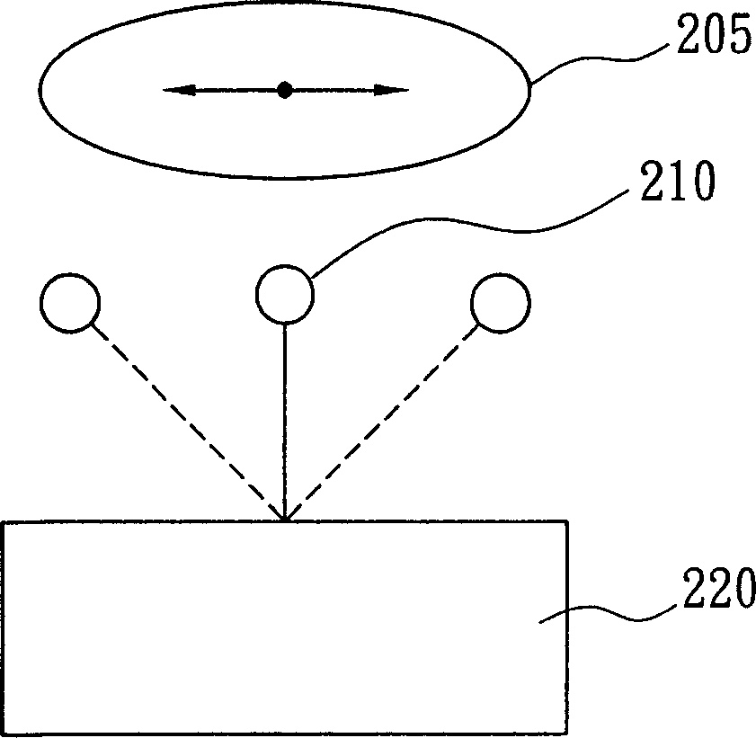
[0028] figure 2 It is a schematic diagram of the read-write head and its carrier in the optical drive. exist figure 2 In general, when the optical disc 205 in the optical drive is off-track, the head 210 in the optical drive and the carrier 220 carrying the head 210 will also move along the direction of the off-track of the optical disc. However, in order to control the read-write head 210 to be at the center of the carrier 220 at any time, the optical drive will control the relative position of the read-write head 210 and the carrier 220 according to a center error signal.

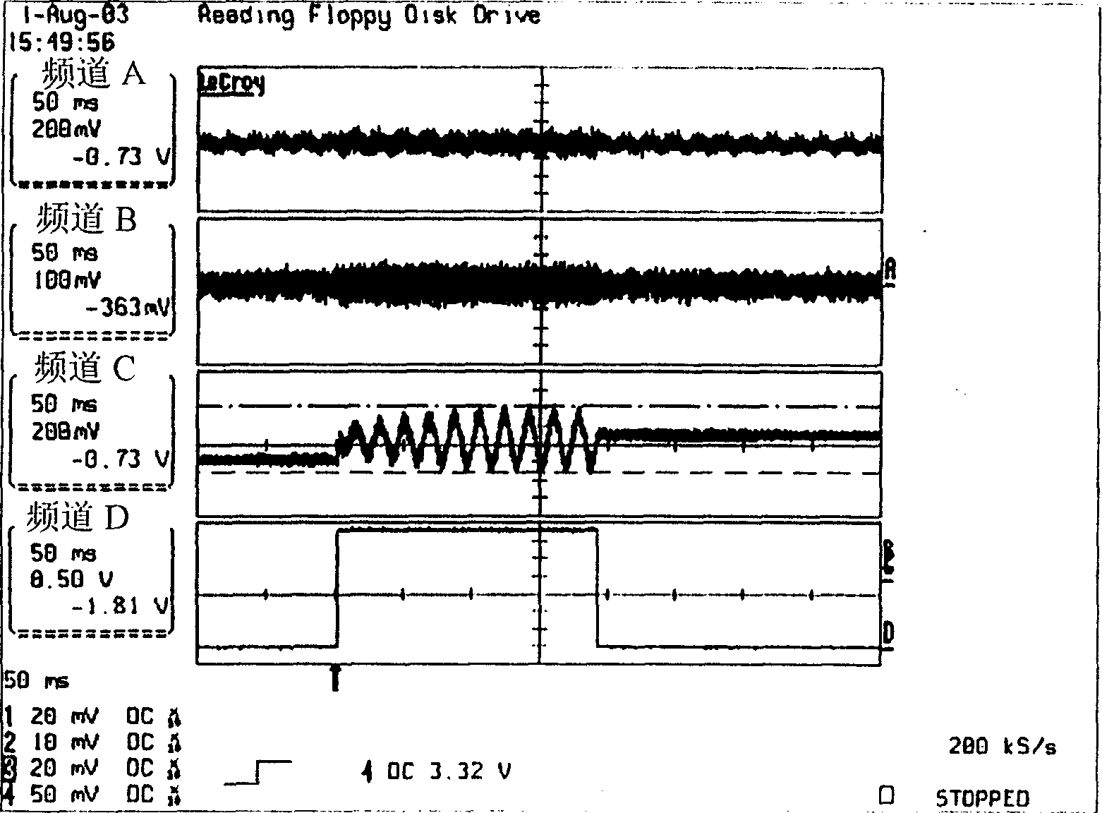
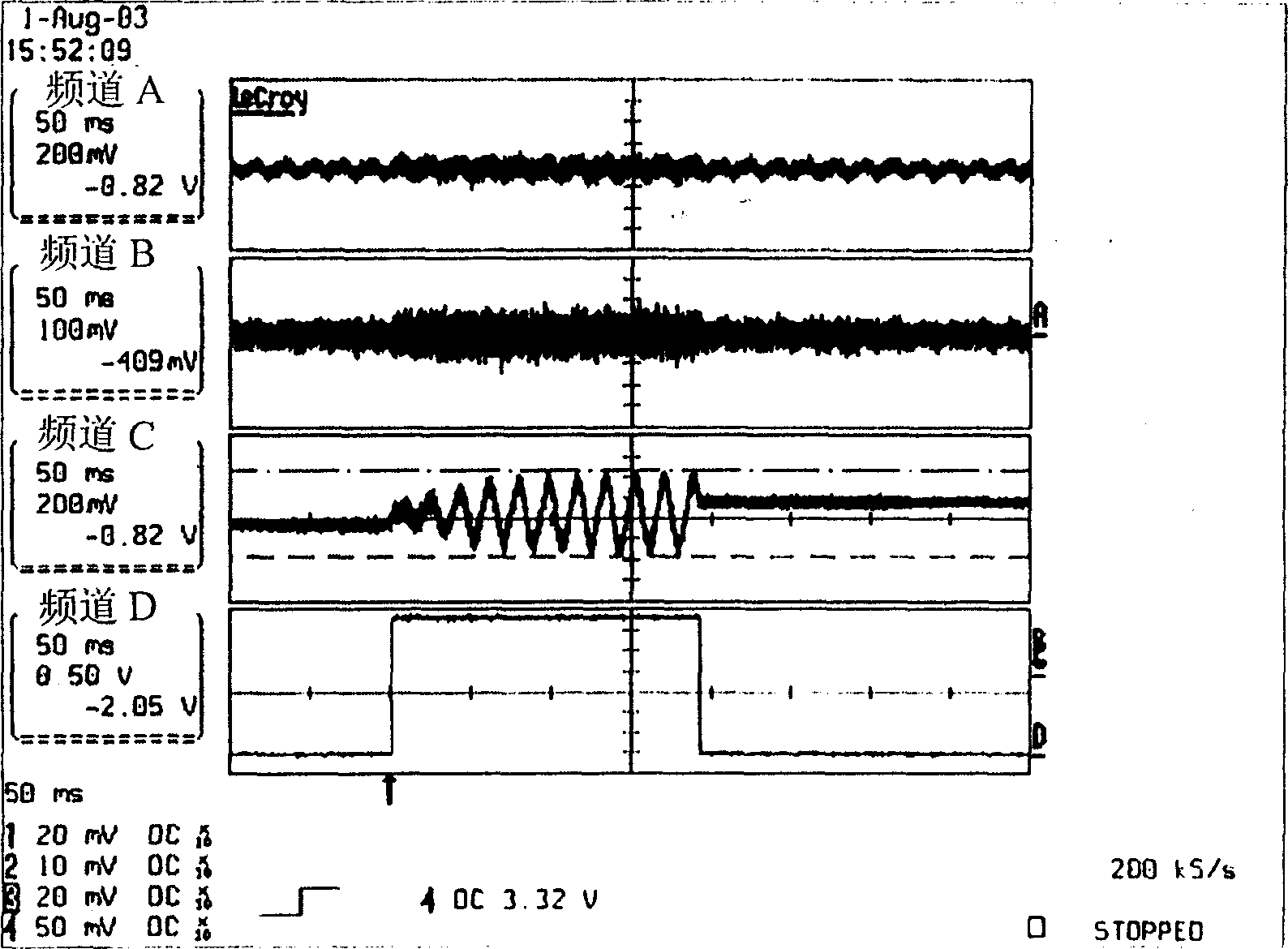
[0029] Because this center error signal will reflect the relative position of the read / write head 210 and the carrier 220 when the optical disc 205 is off track, therefore, this center error signal can also be regarded as a signal reflecting the off track of the optical disc 205 . And in particular, when the optical disc 205 is off-track, the center error signal will be loaded with a frequency conver...


PUM


Abstract

This invention discloses one CD driver bias disc testing method and its device, wherein, it uses the semi-rail signal frequency per time centered as central wrong signals range level as the basis and uses the wrong signals to easily test the bias rail without noisy disturbance to avoid the disc bias.

Description

technical field [0001] The present invention relates to a method and device for detecting disc off-track in an optical drive, in particular to a method and device for detecting disc off-track in an optical drive using the amplitude potential of a center error signal (Center Error) or the frequency of a half-track signal per unit time as an optical drive. basis for the device. Background technique [0002] Generally speaking, because the carrier carrying the optical disc in the optical drive or the track of the optical disc itself is not a true circle, the optical disc is often unable to be fixed on a center of a circle. Also therefore, when the read / write head of the optical drive reads or writes the optical disc, the situation (run out) often occurs easily, and the read / write head of the optical drive cannot read or write to the correct track on the optical disc. [0003] When the optical drive detects that the optical disc it carries is off-track, the corresponding contin...

Claims


Application Information

Patent Timeline
Patent Type & Authority Patents(China)
IPC IPC(8): G11B7/13G11B15/05
Inventor 吴振堂
Owner MEDIATEK INC
Features
  • R&D
  • Intellectual Property
  • Life Sciences
  • Materials
  • Tech Scout
  • Unparalleled Data Quality
  • Higher Quality Content
  • 60% Fewer Hallucinations
Learn More