Low-ripple switch power amplifier for permanent magnet biased electromagnetic-bearing

An electromagnetic bearing and switching power technology, which is applied in the direction of magnetic attraction or thrust holding device, bearing, electromagnet, etc., can solve the problems of increasing switching loss, large iron loss and copper loss of electromagnetic bearing, and large output current ripple. , to achieve the effects of reducing output current ripple, flexible waveform generation, and simple circuit design

Inactive Publication Date: 2006-12-20
BEIHANG UNIV
View PDF0 Cites 1 Cited by
  • Summary
  • Abstract
  • Description
  • Claims
  • Application Information

AI Technical Summary

Problems solved by technology

Although the permanent magnet bias electromagnetic bearing control system can greatly reduce the loss of the switching power amplifier, the output current ripple of the traditional two-level PWM switching power amplifier is very large, which will still cause large iron loss and copper loss in the magnetic bearing. How to reduce the current ripple becomes the key to realize the low ripple loss of the electromagnetic bearing switching power amplifier
[0004] The disadvantage of the existing electromagnetic bearing switching power amplifier is that the current ripple is large, which will cause repeated magnetization loss in the electromagnetic bearing
Usually, the switching frequency of the switching power amplifier can be increased to reduce the ripple of the output current, but a new problem is that while reducing the ripple of the output current, it also increases the switching frequency caused by the frequent switching of the power switch tube. loss

Method used


Image

  • Low-ripple switch power amplifier for permanent magnet biased electromagnetic-bearing
  • Low-ripple switch power amplifier for permanent magnet biased electromagnetic-bearing
  • Low-ripple switch power amplifier for permanent magnet biased electromagnetic-bearing

Examples


Embodiment Construction

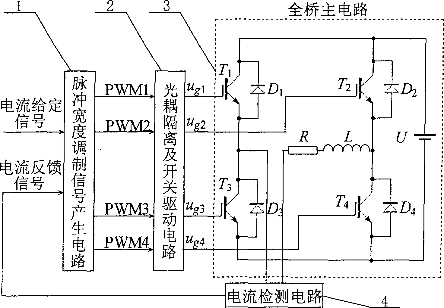
[0012] The block diagram of the circuit structure of the present invention is as figure 1 As shown, it can be divided into four parts, namely pulse width modulation signal generation circuit, optocoupler isolation and switch drive circuit, full bridge main circuit and current detection circuit. The pulse width modulation signal generating circuit is a key component of the present invention, and the present invention is realized by using analog circuits and digital circuits made up of discrete components, and can also be digitally realized by software programming. The optocoupler isolation circuit uses chip 6N137, and the switch drive circuit uses chip IR2110. The current detection circuit adopts the current sensor LA28-NP of LEM Company.

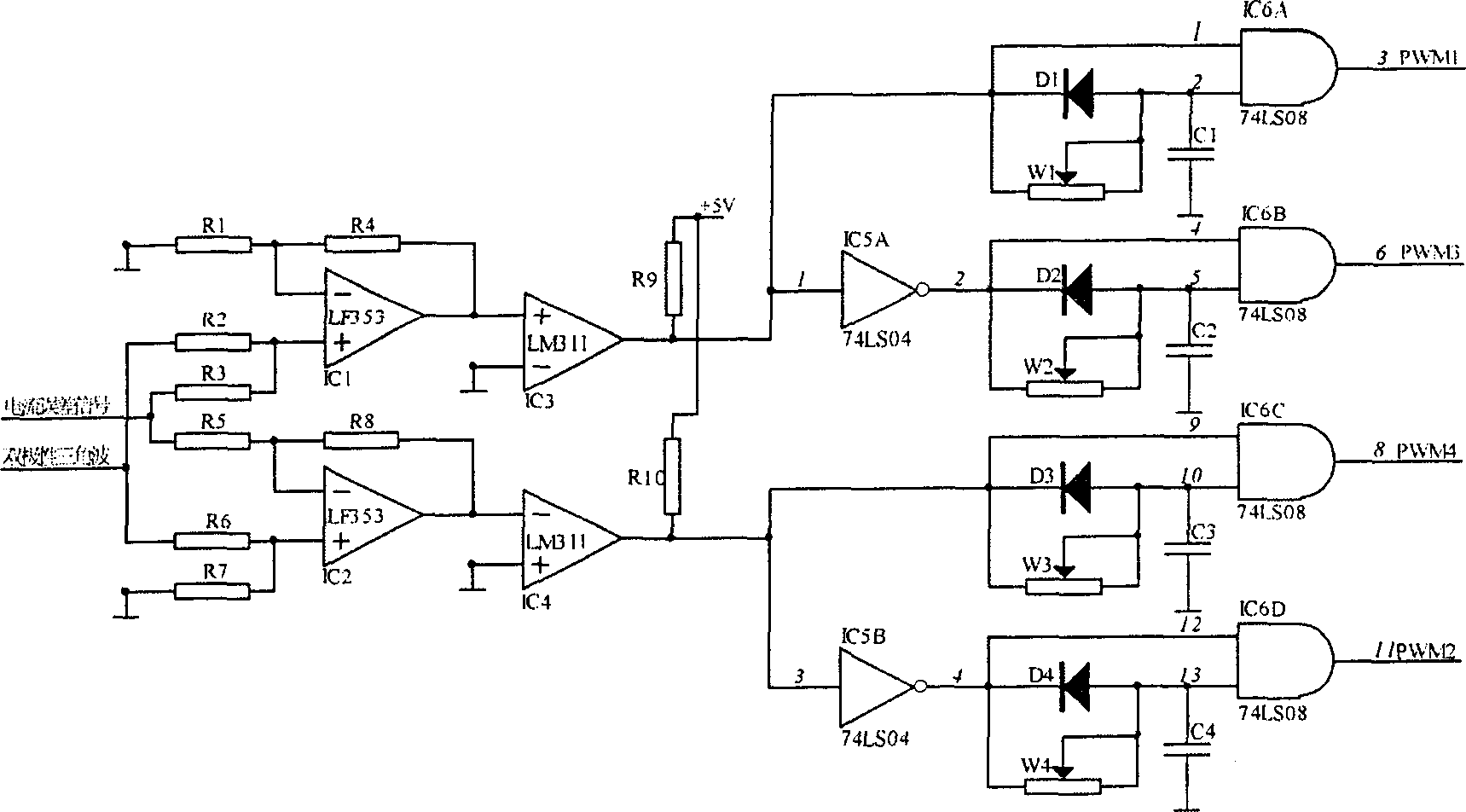
[0013] The following is attached figure 2 , the principle of the PWM modulation circuit adopted in the present invention will be described.

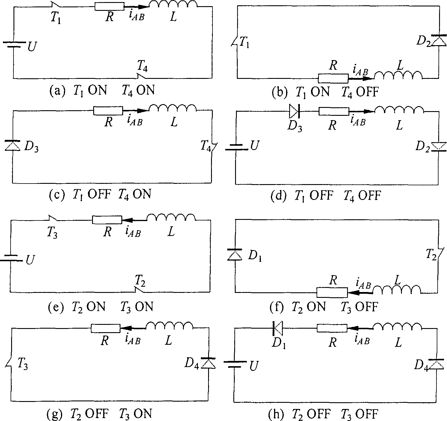
[0014] For the electromagnetic bearing switching power amplifier, through the four power switch...


PUM


Abstract

The invented equipment is in use for controlling current in load coil of electromagnet bearing. The switching power amplifier includes circuit for generating signal of pulse width modulation (PWM), light coupling isolation and switching drive circuit, main circuit of full bridge and current testing circuit. Based on error signal formed from specified signal of current and feedback signal of current, the switching power amplifier carries out PWM. Through light coupling isolation and switching drive circuit, completed PWM signal controls and turns to On / Off of four pieces of power switch tube on two bridge arms of main circuit of full bridge directly. The invention lowers wastage in electromagnet bearing caused by current ripple.

Description

Technical field [0001] The invention relates to a low-ripple switching power amplifier for permanent magnet bias electromagnetic bearings, which is used to control the output current of the electromagnetic bearing coils. Background technique [0002] Electromagnetic bearing is a high-tech electromechanical integration product, which has the advantages of high speed, no friction, long life, no lubrication, no pollution, etc. It has broad application prospects in aerospace, turbomachinery, vacuum technology and high-speed machine tools. . As the actuator of the electromagnetic bearing control system, the power amplifier consumes the most energy. Reducing its power consumption and improving energy conversion efficiency is one of the main purposes of power amplifier design, and it is also the problem that the electromagnetic bearing control system needs to solve to achieve low power consumption. One of the key technologies. [0003] The permanent magnet bias electromagnetic be...

Claims


Application Information

Patent Timeline
Patent Type & Authority Patents(China)
IPC IPC(8): H02N15/00H02M3/155H01F7/18F16C32/04
CPCF16C32/0457
Inventor 张亮刘刚房建成
Owner BEIHANG UNIV
Why Eureka
Try Eureka