Vehicle body structure

A body and vehicle technology, applied in the direction of superstructure, substructure, vehicle parts, etc., can solve the problems such as difficult to fasten the buffer beam

Inactive Publication Date: 2007-03-28
MITSUBISHI JIDOSHA ENG KK +1
View PDF0 Cites 0 Cited by
  • Summary
  • Abstract
  • Description
  • Claims
  • Application Information

AI Technical Summary

Problems solved by technology

In these cases, it is difficult to directly fasten the bumper beam 128 to the front side member 121 and the pillar stay 140 using a stud or the like.

Method used


Image

  • Vehicle body structure
  • Vehicle body structure
  • Vehicle body structure

Examples


Embodiment Construction

[0043] A preferred embodiment of the invention will now be described with reference to the accompanying drawings.

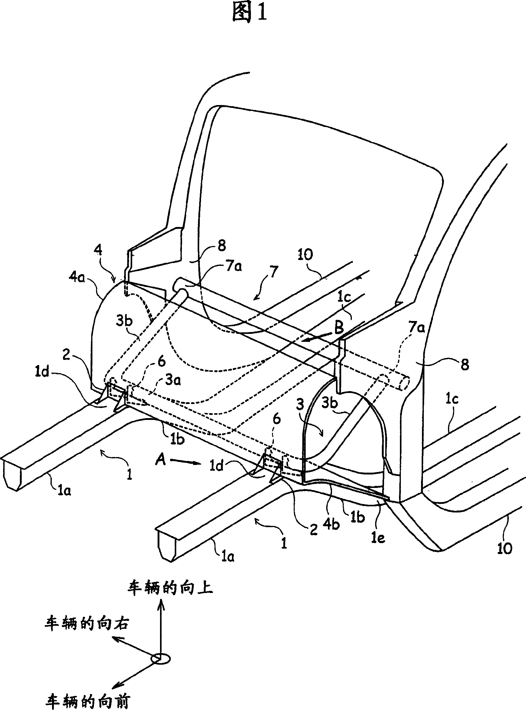
[0044] As shown in FIG. 1, a vehicle using the vehicle body structure of the present invention has a pair of front side members 1 and 1 extending in the lengthwise direction of the vehicle body. left side). Moreover, the vehicle also has a pair of side sills 10 and 10 extending in the lengthwise direction of the vehicle body. One is on the left side, along the width of the body. From the side sills 10 and 10 rise a pair of front pillars 8 and 8 extending upwardly to the roof of the vehicle. And, a deck beam 7 extending in the width direction of the vehicle body is provided between the two front pillars 8 and 8 so as to be connected therebetween, and the connecting portions 7a and 7a on the ends of the deck beam 7 are welded To front uprights 8 and 8.

[0045] A buffer beam 3 is placed between the connecting portions 7a and 7a on the ends of the front side mem...


PUM


Abstract

A structure of a vehicle body is composed of left and right front side members(1) extended longitudinally at the lateral sides of the vehicle body; a deck cross member(7) arranged between left and right front pillars(8) of the vehicle body in a width direction of the vehicle; and a dash cross member(3) coupled to the left and right front side members and disposed in the width direction of the vehicle to connect the deck cross member or the left and right front pillars to the front side member, wherein both ends of the dash cross member are extended toward the left and right front pillars or the deck cross member. The dash cross member is combined to the upside of the front side member in the longitudinal direction in front of the front pillar by brackets(2,6).

Description

technical field [0001] The present invention relates to a vehicle body structure. Background technique [0002] Various techniques have been developed for providing a front side member (a side member of a front part of a vehicle body) with a shock absorbing capability and for providing a body part with rigidity around a passenger compartment, To improve the safety performance in the event of a collision. More specifically, the impact of the front side member is like an accordion in a crash to absorb the shock applied thereto, which should be transmitted to the vehicle cabin, so that the safety of the cabin is improved. [0003] Here, providing a body structure with two such contradictory functions, an impact-absorbing function and an impact-resistant function, is an important task to be solved. [0004] Considering this point, Japanese Patent Publication No. 2000-153779 shown in FIG. 8 discloses a front side member 121 comprising: a front portion 121a extending horizontall...

Claims


Application Information

Patent Timeline
Patent Type & Authority Patents(China)
IPC IPC(8): B62D25/14B62D21/00B62D25/08
CPCB62D25/082B62D25/145B62D25/02B62D25/04
Inventor 黑川博幸横田义则尾崎照夫
Owner MITSUBISHI JIDOSHA ENG KK
Why Eureka
Try Eureka