Optic disc device

An optical disc device and optical disc technology, applied to optical recording systems, optical recording/reproduction, optical recording/reproduction/erasing methods, etc., can solve the problems of inability to correctly control the amount of inclination, reduction of light reflected by photodetectors, laser Low power can not form marks and other problems

Inactive Publication Date: 2003-04-09
TEAC CORP
View PDF0 Cites 4 Cited by
  • Summary
  • Abstract
  • Description
  • Claims
  • Application Information

AI Technical Summary

Problems solved by technology

[0009] Although the laser is obliquely incident on the disc, the laser power on the disc surface is low and marks cannot be formed, but the oblique laser incident on the disc also reduces the amount of reflected light to the photodetector
In other words, the increase in reflectivity caused by the insufficiency of the incident laser light due to the inclination of its power, and the decrease in the reflected light itself due to the inclination, both cancel each other out. Therefore, the composition of controlling the reflected light amount of the laser light is lower than the usual value. The risk of not being able to control the amount of inclination correctly

Method used


Image

  • Optic disc device
  • Optic disc device
  • Optic disc device

Examples


Embodiment 1

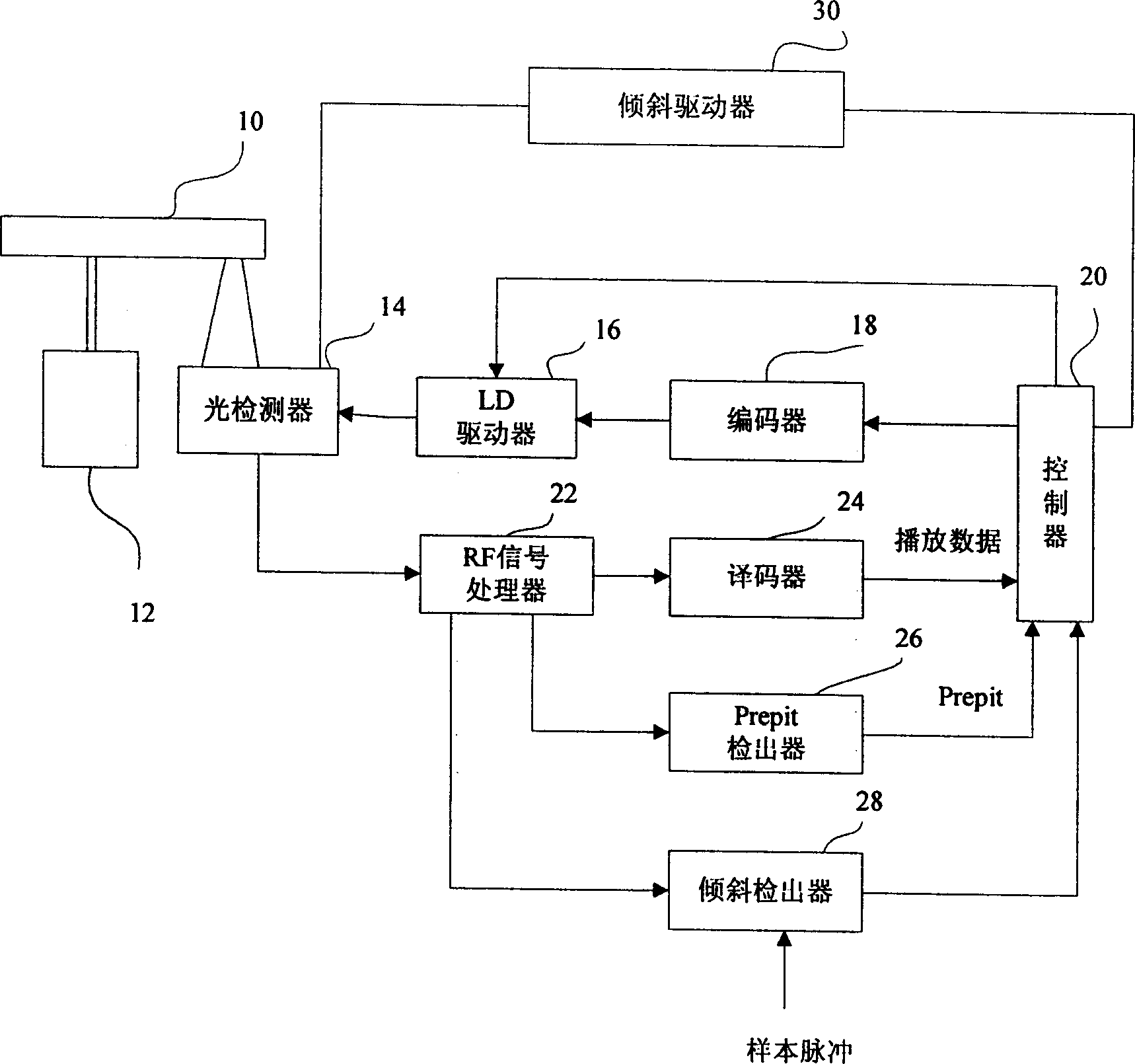
[0051] figure 1 is a block diagram showing the configuration of the optical disc device of this embodiment. The optical disc 10 is driven by a spindle motor 12 to rotate in CAV (or CLV).

[0052]The optical pick-up head 14 is arranged facing the optical disc 10, and can irradiate the optical disc 10 with laser recording data at a recording power, and can also play the recorded data with a laser at a playback power. During recording, the recording data from the controller 20 is modulated by the encoder 18 and converted into a driving signal by the LD driver to drive the laser diode (LD) of the optical pickup 14 . During playback, the four-divided photodetector in the optical pickup head 14 converts the reflected light into an electrical signal, which is supplied to the RF signal processor 22 , and then demodulated by the decoder 24 , and then converted into playback data and supplied to the controller 20 .

[0053] The RF signal processor 22 includes an amplifier or an equal...

Embodiment 2

[0075] FIG. 8 is a time chart of the detection processing by the inclination detector 28 of this embodiment. In Example 1, at the beginning of the marking period, the sample maintains the amount of reflected light when the pinhole is not formed, and controls the amount of inclination to maximize the reflected light signal. However, in this embodiment, the sample maintains the reflected optical signal during the gap period of the recording pulse. During the void, no pinholes are formed as described above, and the disc is irradiated with laser light at playback power. Therefore, the amount of reflected light of the laser light at the playback power is not affected by the pinhole, but only increases or decreases according to the inclination of the optical disc 10 . Therefore, during the gap period, the sample maintains the reflected light signal, and the tilt is controlled to maximize the reflected light signal, so that the optical axis of the laser light can be adjusted to be a...

Embodiment 3

[0079] FIG. 9 is a time chart of detection processing by the inclination detector 28 of this embodiment. This embodiment is set to the form of DVD-RW, and the laser can be adjusted into three stages of erasing power, recording power and playing power. When the optical disc that has recorded data is recording data again, it is necessary to use the erasing power to erase the data, and then use the recording power to record the data.

[0080]As shown in FIG. 9, laser light of erasing power Pe is irradiated during the space period, and plural laser light including recording power Pw are irradiated during mark period to form pinholes. The recording power Pw alternates with the playback power Pr during marking. In this embodiment, the tilt detector 28 is also the same as in Embodiment 2, and the sample maintains a reflected light signal during the gap period, and supplies the level to the controller 20 . The erasing power is irradiated during the gap period. As long as a sufficien...


PUM


Abstract

This invention provides a way to control the tilt of optical disk for an optical disk device that can read and write on an optical disk. The control process includes: Optical pick-up 14, output signals of reflecting beams to a tilt detector 28. Tilt detector 28, sample-holds the signal level of reflecting beams of the write power before pits are formed, and outputs the signal level to a controller 20. The controller 20 changes the tile of the optical pickup 14 into three different states, and compares sample hold valves of each state, and adjusts the tilt to the state that generates the maximum signal level. Since the pits are not formed at that time, the signal of reflecting beams have not affected by pits, the signal level reflects only to the tilt of optical disk 10. This invention enables to control the tilt of the optical disk 10 precisely.

Description

technical field [0001] The invention relates to an optical disc device, in particular to the field of adjusting the optical axis inclination of the optical disc and laser. Background technique [0002] Recordable optical disk devices such as CD-R / RW or DVD-R / RW have the problem of not being able to stably record and play data when the optical axis of the optical disk and the laser beam are tilted. In this regard, it has been previously proposed to install a tilt sensor in the optical disc device to detect the tilt amount, so as to adjust the tilt of the optical pick-up head. [0003] Figure 10 What is shown is a simple configuration diagram of a commonly used optical disc device with a tilt sensor. The optical disc 10 is rotated by a spindle motor 12 , and an optical pick-up head 14 is disposed facing the optical disc 10 . The reflected light after the laser light of the optical pickup 14 irradiates the optical disc 10 is converted into an electrical signal by the photode...

Claims


Application Information

Patent Timeline
Patent Type & Authority Applications(China)
IPC IPC(8): G11B7/095G11B7/00G11B7/0045G11B7/006G11B21/02
CPCG11B7/0062G11B7/00456G11B7/0956G11B7/095
Inventor 武田直人
Owner TEAC CORP
Why Eureka
Try Eureka