Optic disc device
An optical disc device and optical disc technology, applied to optical recording systems, optical recording/reproduction, optical recording/reproduction/erasing methods, etc., can solve the problems of inability to correctly control the amount of inclination, reduction of light reflected by photodetectors, laser Low power can not form marks and other problems
- Summary
- Abstract
- Description
- Claims
- Application Information
AI Technical Summary
Problems solved by technology
Method used
Image
Examples
Embodiment 1
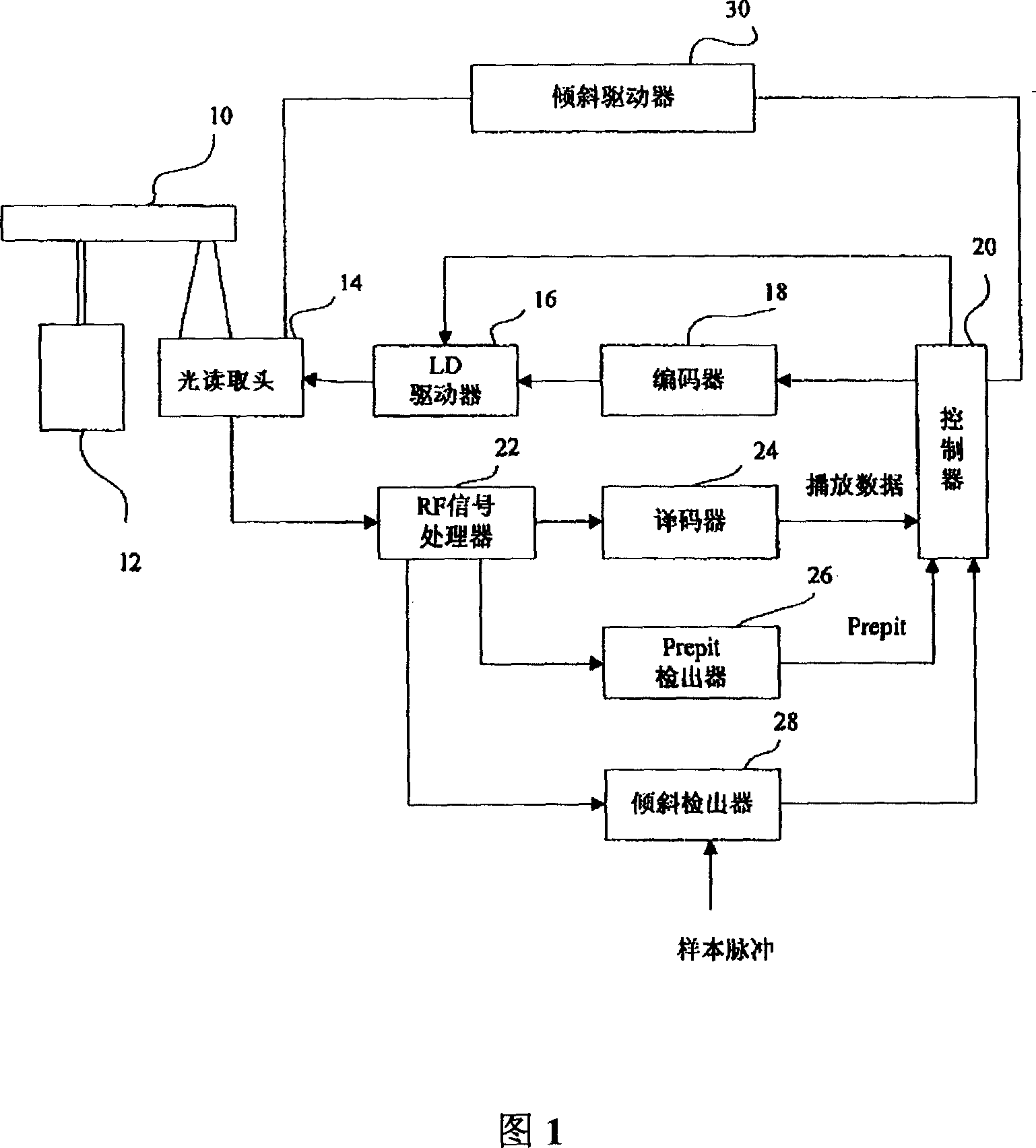
[0052] FIG. 1 is a block diagram showing the configuration of an optical disc device of this embodiment. The optical disc 10 is driven by a spindle motor 12 to rotate in CAV (or CLV).
[0053] The optical pick-up head 14 is arranged facing the optical disc 10, and can irradiate the optical disc 10 with laser recording data at a recording power, and can also play the recorded data with a laser at a playback power. During recording, the recording data from the controller 20 is modulated by the encoder 18 and converted into a driving signal by the LD driver to drive the laser diode (LD) of the optical pickup 14 . During playback, the four-divided photodetector in the optical pickup head 14 converts the reflected light into an electrical signal, which is supplied to the RF signal processor 22 , and then demodulated by the decoder 24 , and then converted into playback data and supplied to the controller 20 .
[0054]The RF signal processor 22 includes an amplifier or an equalizer,...
Embodiment 2
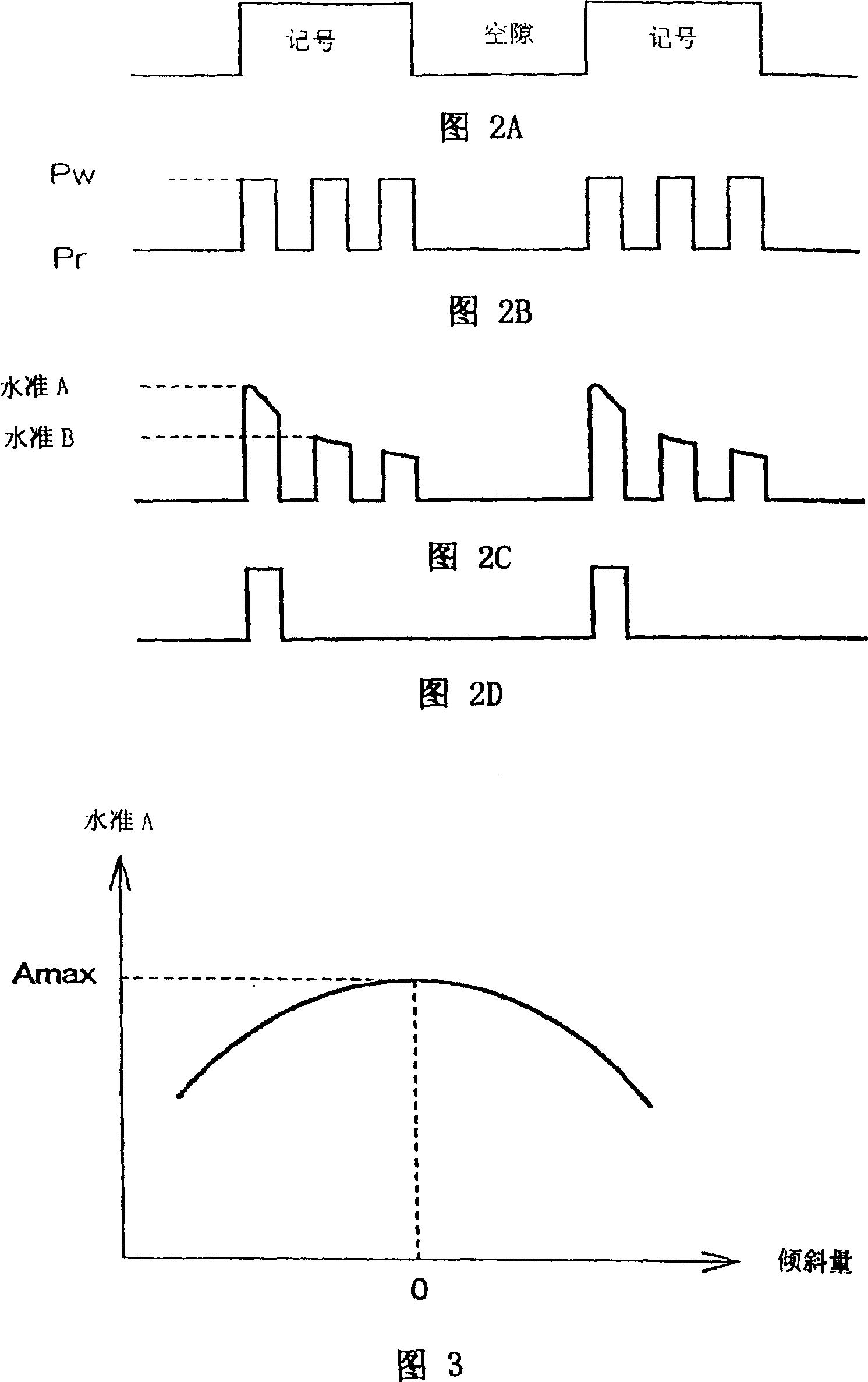
[0076] FIG. 8 is a time chart of the detection processing by the inclination detector 28 of this embodiment. In Example 1, at the beginning of the marking period, the sample maintains the amount of reflected light when the pinhole is not formed, and controls the amount of inclination to maximize the reflected light signal. However, in this embodiment, the sample maintains the reflected optical signal during the gap period of the recording pulse. During the void, no pinholes are formed as described above, and the disc is irradiated with laser light at playback power. Therefore, the amount of reflected light of the laser light at the playback power is not affected by the pinhole, but only increases or decreases according to the inclination of the optical disc 10 . Therefore, the sample maintains the reflected light signal during the gap period, and the tilt is controlled to maximize the reflected light signal, so that the optical axis of the laser light can be adjusted to be ap...
Embodiment 3
[0080] FIG. 9 is a time chart of detection processing by the inclination detector 28 of this embodiment. This embodiment is set to the form of DVD-RW, and the laser can be adjusted into three stages of erasing power, recording power and playing power. When the optical disc that has recorded data is recording data again, it is necessary to use the erasing power to erase the data, and then use the recording power to record the data.
[0081] As shown in FIG. 9, laser light of erasing power Pe is irradiated during the space period, and plural laser light including recording power Pw are irradiated during mark period to form pinholes. The recording power Pw alternates with the playback power Pr during marking. In this embodiment, the tilt detector 28 is also the same as in Embodiment 2, and the sample maintains a reflected light signal during the gap period, and supplies the level to the controller 20 . The erasing power is irradiated during the gap period. As long as a sufficie...
PUM
 Abstract
Description
Claims
Application Information
 - R&D
- Intellectual Property
- Life Sciences
- Materials
- Tech Scout
- Unparalleled Data Quality
- Higher Quality Content
- 60% Fewer Hallucinations
Browse by: Latest US Patents, China's latest patents, Technical Efficacy Thesaurus, Application Domain, Technology Topic, Popular Technical Reports.
© 2025 PatSnap. All rights reserved.Legal|Privacy policy|Modern Slavery Act Transparency Statement|Sitemap|About US| Contact US: help@patsnap.com


