Electric dust remover and head of electric dust remover

A vacuum cleaner and vacuum head technology, applied in the directions of vacuum cleaners, applications, suction nozzles, etc., can solve problems such as difficulties, multiplication of miscellaneous bacteria, insufficient deodorization measures, etc.

Inactive Publication Date: 2003-07-09
PANASONIC CORP
View PDF1 Cites 4 Cited by
  • Summary
  • Abstract
  • Description
  • Claims
  • Application Information

AI Technical Summary

Problems solved by technology

Although various studies have been carried out on this existing electric vacuum cleaner, the dust suction head 4 can suck dust with high efficiency, intercept the sucked dust with high efficiency, and make the dust not as far as possible. It is discharged, but it is extremely difficult to trap human hair, dust, ticks, pollen, mildew, bacteria, household dust and other relatively fine dust
[0005] In addition, since the anti-odor measures for the peculiar smell of the dust trapped and accumulated by the dust collector 12 are not sufficient, when the electric vacuum cleaner is started, the above-mentioned peculiar smell will be discharged from the exhaust port 9 to the outside of the main machine body.
In addition, when the dust accumulated in the dust collecting device 12 is left for a long time, there will be bacteria breeding in it. Once the electric vacuum cleaner is started, the bacteria will fly outside through the exhaust port 9, which is very unhygienic.

Method used


Image

  • Electric dust remover and head of electric dust remover
  • Electric dust remover and head of electric dust remover
  • Electric dust remover and head of electric dust remover

Examples


Embodiment 1

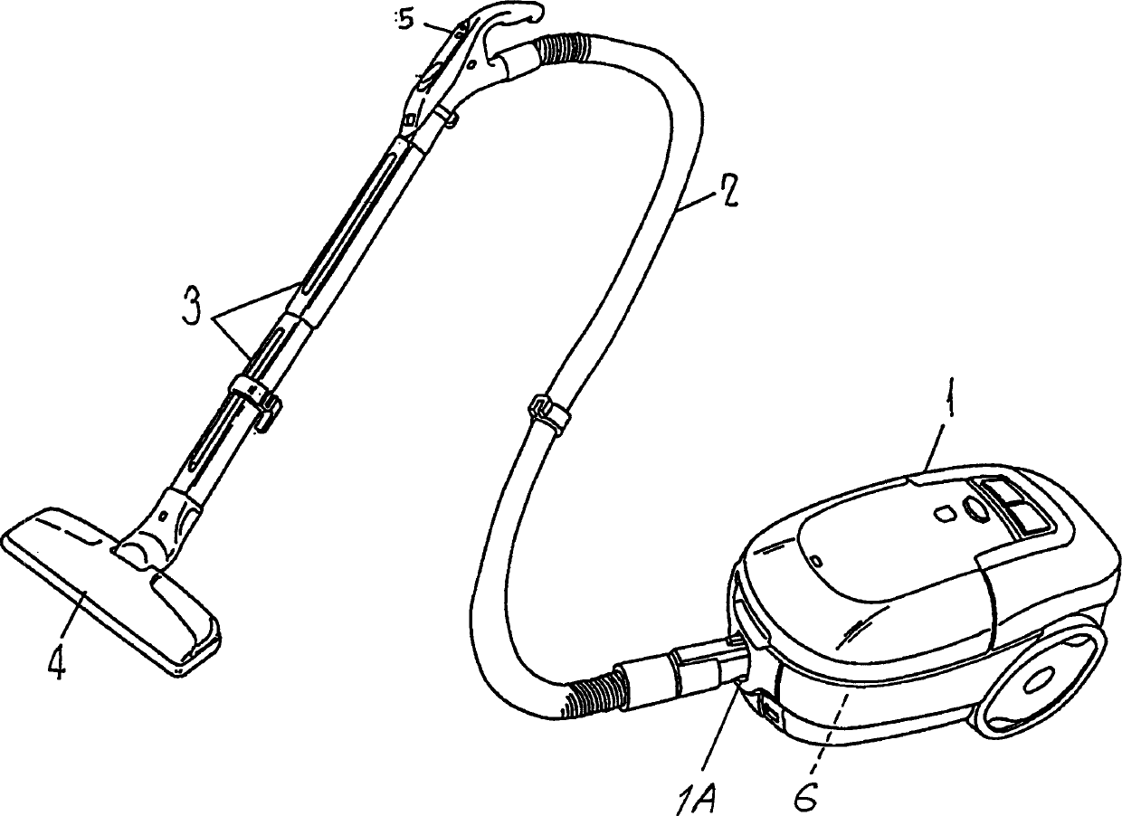
[0029] Hereinafter, Embodiment 1 of the present invention will be described with reference to FIG. 3 . The overall structure of the electric vacuum cleaner in this embodiment is the same as that of the conventional device shown in FIG. 1 .

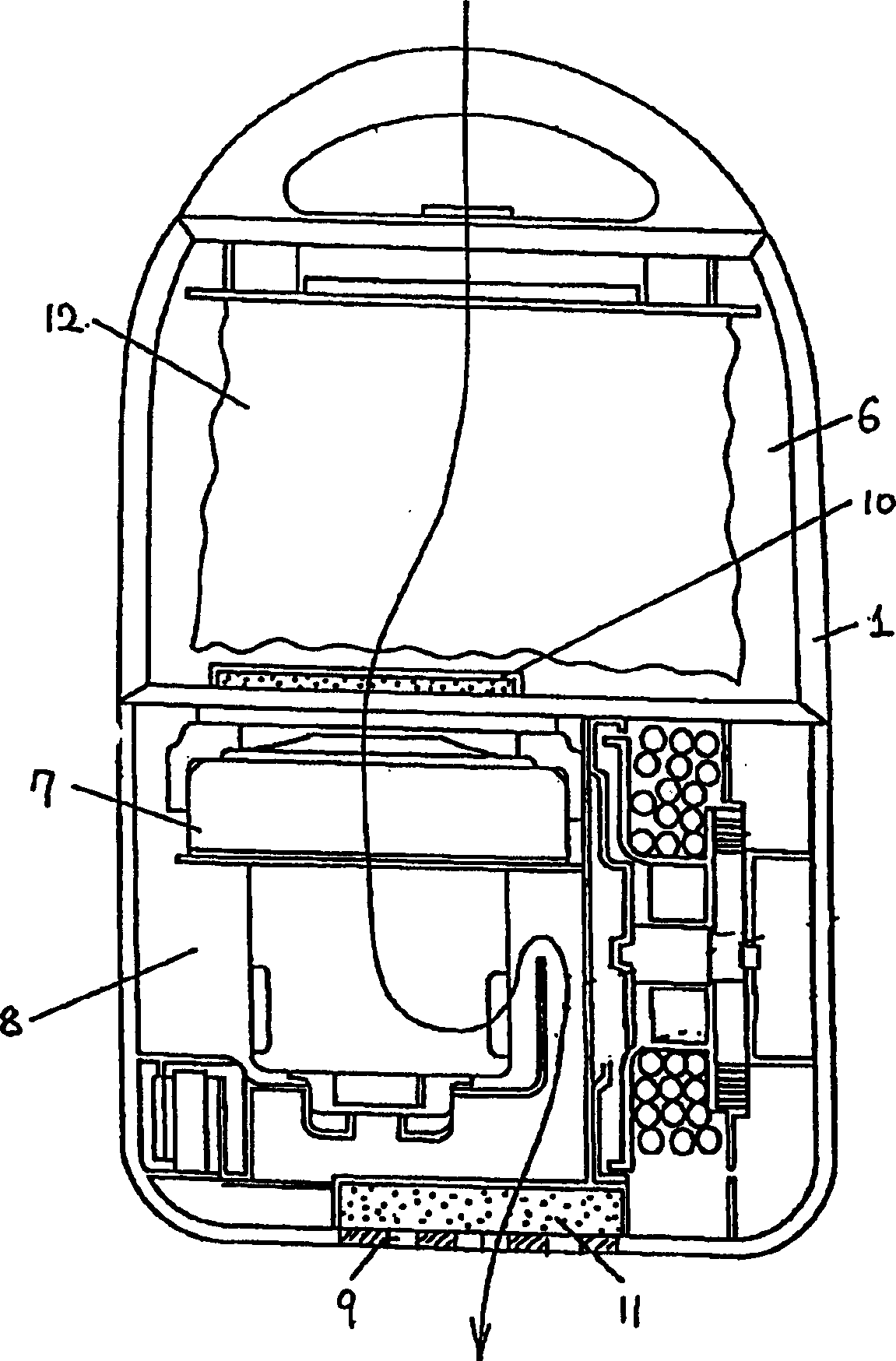
[0030] As shown in Figure 3, the main body 1 of the electric vacuum cleaner is provided with: a dust collection chamber 6; a dust collection device 12 which is arranged in the dust collection chamber 6 and is used to intercept / collect dust and is composed of a dust collection bag; An electric blower 7 for forcibly sucking air from dust and an exhaust port 9 serving as an exhaust part for discharging the sucked air to the atmosphere.

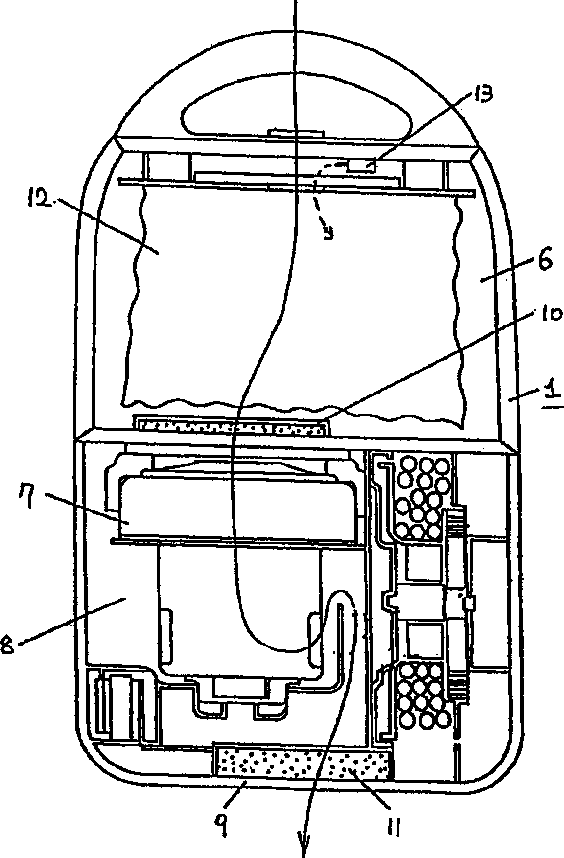
[0031] In addition, an ion generator 13 capable of generating negative ions, positive ions, or both positive and negative ions is disposed at a position between the cleaning head 4 and the upstream side of the electric blower 7 . In this embodiment, it is arranged inside the dust collection chamber 6, but as...

Embodiment 2

[0034] Hereinafter, Embodiment 2 of the present invention will be described with reference to FIG. 4 . Components that are the same as those of the conventional vacuum cleaner and the above-mentioned embodiments are assigned the same names and symbols, and their descriptions are omitted.

[0035] An ion generator 13 capable of generating negative ions, positive ions, or both positive and negative ions is provided on the hand-operated portion 5 located between the downstream side of the cleaning head 4 and the upstream side of the dust collection chamber 6 . In this way, various accessories such as flexible pipes and extension pipes connected between the suction head 4 and the main body 1 of the electric vacuum cleaner can produce antibacterial and deodorizing effects, and can also achieve effects such as reducing dust adhesion.

Embodiment 3

[0037] Next, Embodiment 3 of the present invention will be described with reference to FIG. 5 . Components that are the same as those of the conventional vacuum cleaner and the above-mentioned embodiments are assigned the same names and symbols, and their descriptions are omitted.

[0038] As shown in FIG. 5 , the installed ion generator 13 supplies negative ions, positive ions, or both positive and negative ions to the dust collecting device 12 installed in the dust collecting chamber 6 or to the inside of the dust collecting chamber 6 .

[0039] After adopting the above-mentioned structure, since the ions are concentrated and directly emitted to the place where the dust is trapped and stored, the deodorizing, antibacterial and dust-removing effects of various ions can be more effectively exerted as described above.


PUM


Abstract

Disclosed are an electric dust remover and a head of electric dust remover. The electric dust remover includes: an electric blower (7) for generating a suction air flow for drawing in dirt; a dust collecting chamber (6) communicating with the electric blower (7), for catching and collecting dust; an exhaust portion (9) for exhausting air from the motor driven blower (7) into the atmosphere; a suction head (4) in communication with the dust collecting chamber (6) and an ion generator (13) for generating negative, positive, or both ions, disposed on the a part of a communication passage between the suction head (4) and the exhaust portion (9). Ions generated by the ion generator (13) can deodorize the dust and improve dust collecting performance for collecting dust from a surface to be cleaned.

Description

technical field [0001] The invention relates to an electric vacuum cleaner equipped with an ion generating body capable of generating negative ions or positive ions or both positive and negative ions and a suction head for the electric vacuum cleaner. Background technique [0002] An example of an existing electric vacuum cleaner is shown in Japanese Patent Laying-Open No. 62-109531, and Fig. 1 and Fig. 2 show its main structure. [0003] Fig. 1 is the overall structural diagram of the electric vacuum cleaner, and Fig. 2 is a structural diagram of the main body of the electric vacuum cleaner. In the main body 1 of the electric vacuum cleaner, there is an electric blower chamber 8 with an electric blower 7 inside and a collector located upstream of the electric blower 7. Dust room6. A dust collecting device 12 made of a paper bag or the like is housed in the dust collecting chamber 6 . One end of the hose 2 is connected to the connecting port 1A communicating with the dust ...

Claims


Application Information

Patent Timeline
Patent Type & Authority Applications(China)
IPC IPC(8): A47L7/04A47L9/04A47L9/06
CPCA47L9/0488A47L7/04A47L9/0613A47L9/0411A47L9/06
Inventor 副岛雅邦近藤也寸志谷口善宏吉田良平澁谷昌树山口诚二梶川三郎北村秀典浦谷裕之藤田孝一石川晴香
Owner PANASONIC CORP
Why Eureka
Try Eureka