

Method for exploiting and building tide driftage brook
A tidal and tidal level technology, applied in buildings, artificial waterways, hydropower stations, etc., can solve problems such as difficulty in enjoying rafting and few streams
- Summary
- Abstract
- Description
- Claims
- Application Information
AI Technical Summary
Problems solved by technology
Method used
Image

Examples
Embodiment Construction
[0013] Several embodiments are described below one by one.
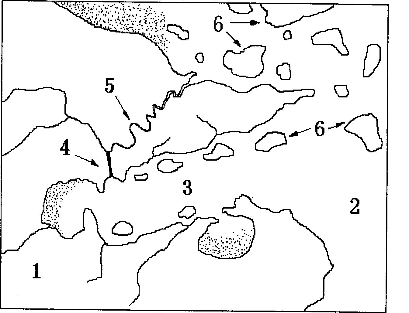
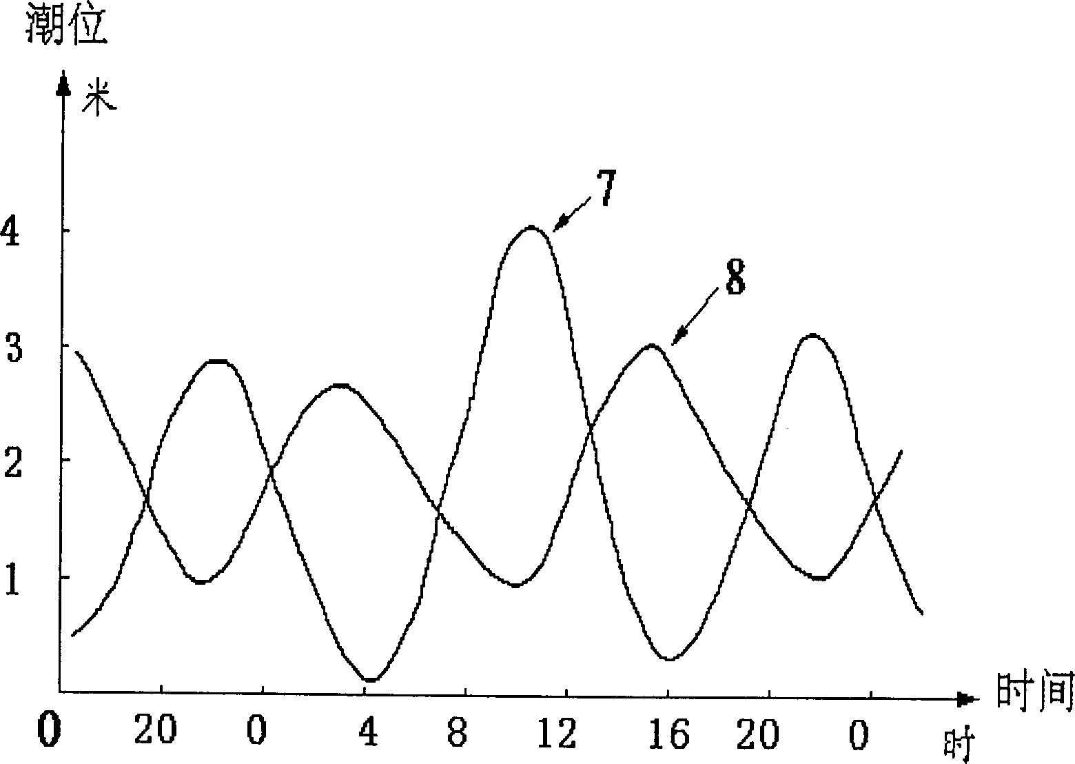
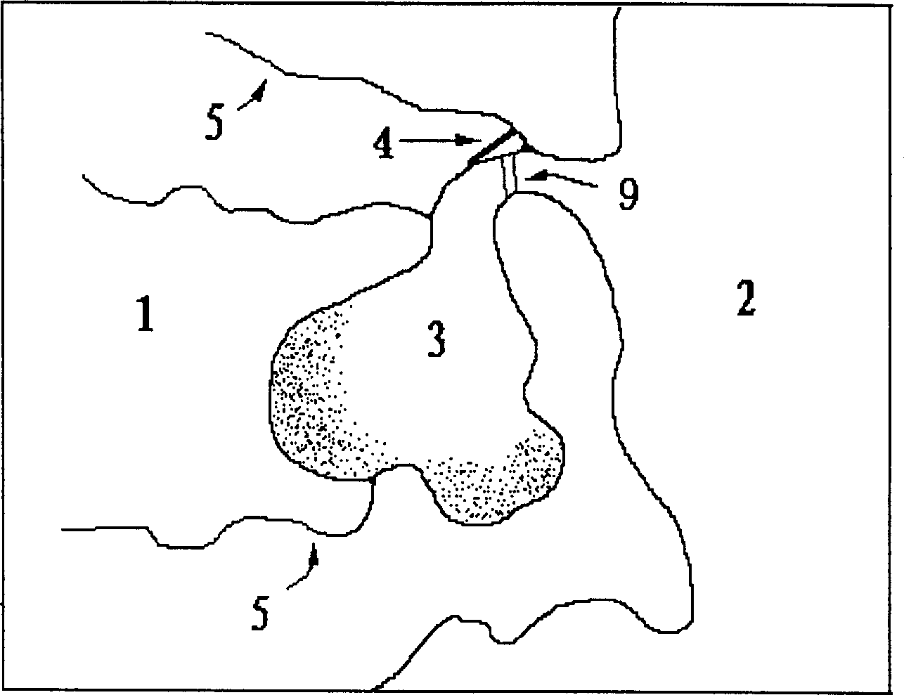
[0014] figure 1 , figure 2 In the middle, the mainland 1 has a large bay 3 and a tidal river 5 that separate out there. Although there are many islands and reefs 6 inside and outside the bay 3, it is open to the open sea 2. The tide is basically synchronized with the open sea and the bottom of the bay The rise and fall of the tide level is greater, manifested as a real-time rise and fall curve7 with large fluctuations; the tide river 5 has many islands and reefs 6 outside the estuary, and because of the twists and turns of the river and the discharge of fresh water upstream, the rising and falling tides are damped, and the tides in the middle reaches are relatively high. The sea 2 has a great lag and tends to be flat, and it appears as a real-time rise and fall curve 8 that is almost opposite to the real-time rise and fall curve 7 of the sea 2 (which is also the bay 3). Therefore, in the valley or low hill between the...
PUM
 Abstract
Description
Claims
Application Information