Optical recording medium and misalignment measuring instrument using the same
An optical recording medium and detection device technology, which is applied to optical record carriers, optical recording/reproducing, data recording, etc., can solve problems such as accuracy deterioration, and achieve the effect of increasing recording capacity
- Summary
- Abstract
- Description
- Claims
- Application Information
AI Technical Summary
Problems solved by technology
Method used
Image
Examples
Embodiment 1
[0065] Embodiment 1 illustrates an example of an optical recording medium related to the present invention.
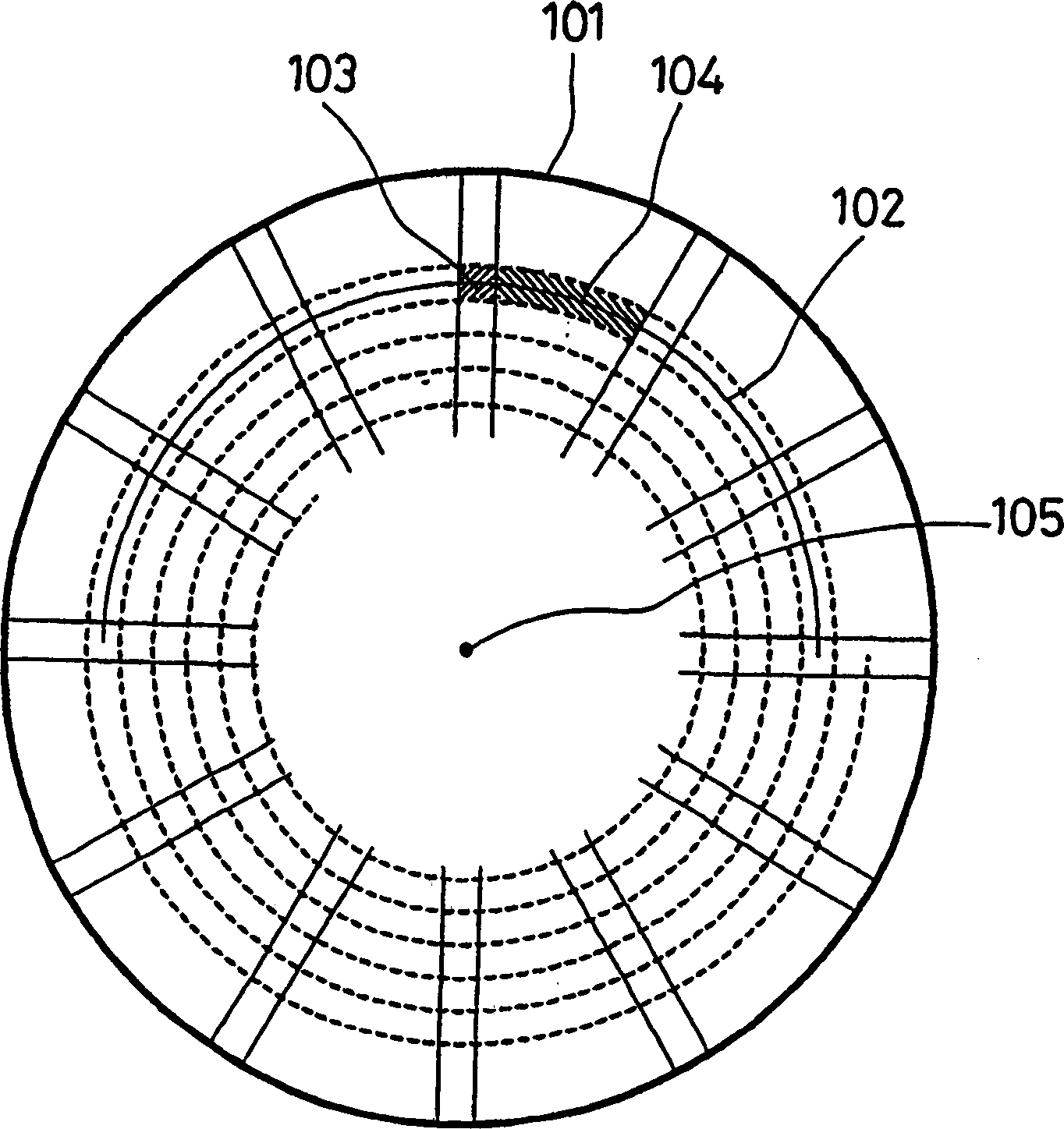
[0066] figure 1 It is a schematic plan view showing the structure of the optical recording medium 101 according to Embodiment 1 of the present invention.
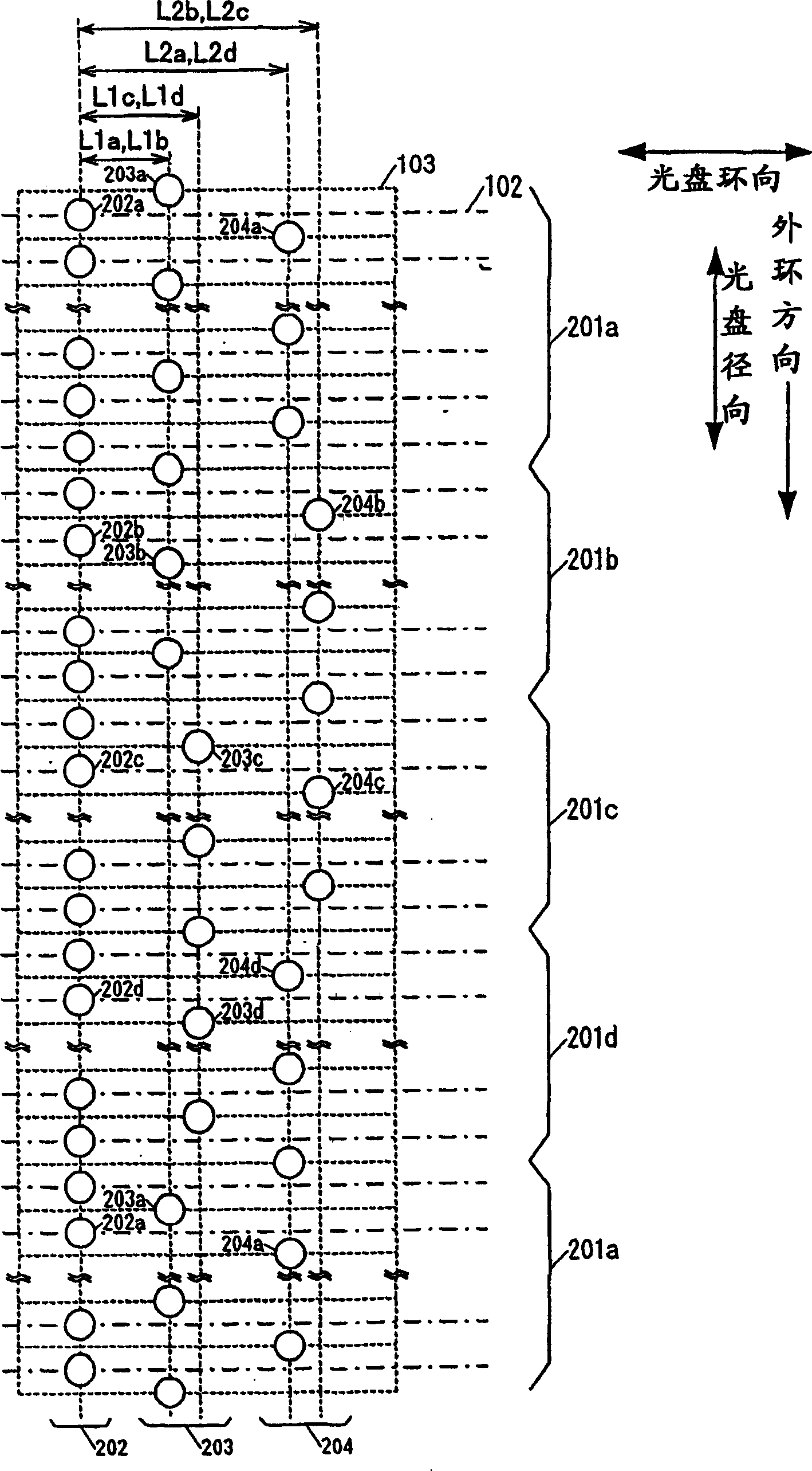
[0067] figure 1 Among them, the optical recording medium 101 is in the shape of a disk, and is provided with a spiral imaginary groove center line 102 ( figure 1 only partially shown). Moreover, on the optical recording medium 101, the servo area 103 and the data area 104 are arranged alternately in the circumferential direction of the disc. Among them, the data area 104 is an area for recording and reproducing information. There are N number of servo areas 103 and data areas 104 respectively (N is an integer greater than or equal to 500, 1280 in this example).
[0068] also, figure 1 The disc center 105 in is a virtual point located at the center of the disc-shaped optical recording medium 101 .
[0069]...
Embodiment 2
[0098] In Embodiment 2, an example of the eccentricity detecting device using the optical recording medium according to the above-mentioned Embodiment 1 will be described.
[0099] Figure 5 It is a schematic block diagram showing a configuration example of an eccentricity detection device according to Embodiment 2 of the present invention.
[0100] Figure 5 Among them, the eccentricity detection device 500 includes an optical recording medium 101 , a detection circuit 501 , a tracking error generation circuit 502 , a direction detection unit 503 , a pattern counting unit 504 , and an eccentricity calculation unit 505 . Figure 5 The optical recording medium 101 is the same as the optical recording medium 101 described in the first embodiment.
[0101] When the disc center of the optical recording medium 101 is eccentric to the center of the data area, the optical spot and the optical recording medium 101 irradiated along the groove center line 102 and read out the data sig...
Embodiment 3
[0140] Hereinafter, another example of the optical recording medium of the present invention will be described using Example 3.
[0141] Figure 14 A schematic plan view showing the structure of an optical recording medium 110 according to Embodiment 3 of the present invention.
[0142] Figure 14 Among them, the optical recording medium 101 is in the shape of a disk, and is provided with a spiral imaginary groove center line 102 ( Figure 14 only part of it is shown). In addition, on the optical recording medium 101, servo areas 103 and data areas 104 are alternately arranged in the circumferential direction of the optical disc. Among them, the data area 104 is an area for recording and reproducing information. There are N number of servo areas 103 and data areas 104 (N is an integer greater than 500, here is 1280).
[0143] and, Figure 14 The disc center 105 in is a virtual point located at the center of the disc-shaped optical recording medium 101 .
[0144] The gro...
PUM
 Abstract
Description
Claims
Application Information
 - R&D
- Intellectual Property
- Life Sciences
- Materials
- Tech Scout
- Unparalleled Data Quality
- Higher Quality Content
- 60% Fewer Hallucinations
Browse by: Latest US Patents, China's latest patents, Technical Efficacy Thesaurus, Application Domain, Technology Topic, Popular Technical Reports.
© 2025 PatSnap. All rights reserved.Legal|Privacy policy|Modern Slavery Act Transparency Statement|Sitemap|About US| Contact US: help@patsnap.com


