Vortex compressor

A scroll compressor, scroll technology, applied in the direction of rotary piston machinery, rotary piston pump, mechanical equipment, etc., can solve the problems of increased sliding loss, increased number of parts, decreased production efficiency, etc., to achieve mechanical efficiency The effect of improving, increasing the number of parts, and improving the efficiency of the machine

Inactive Publication Date: 2003-12-03
PANASONIC CORP
View PDF1 Cites 6 Cited by
  • Summary
  • Abstract
  • Description
  • Claims
  • Application Information

AI Technical Summary

Problems solved by technology

However, there are problems of increased sliding loss due to the contact of the tip seal, an increase in the number of parts, and a decrease in production efficiency due to an increase in processing steps.

Method used


Image

  • Vortex compressor
  • Vortex compressor
  • Vortex compressor

Examples


Embodiment Construction

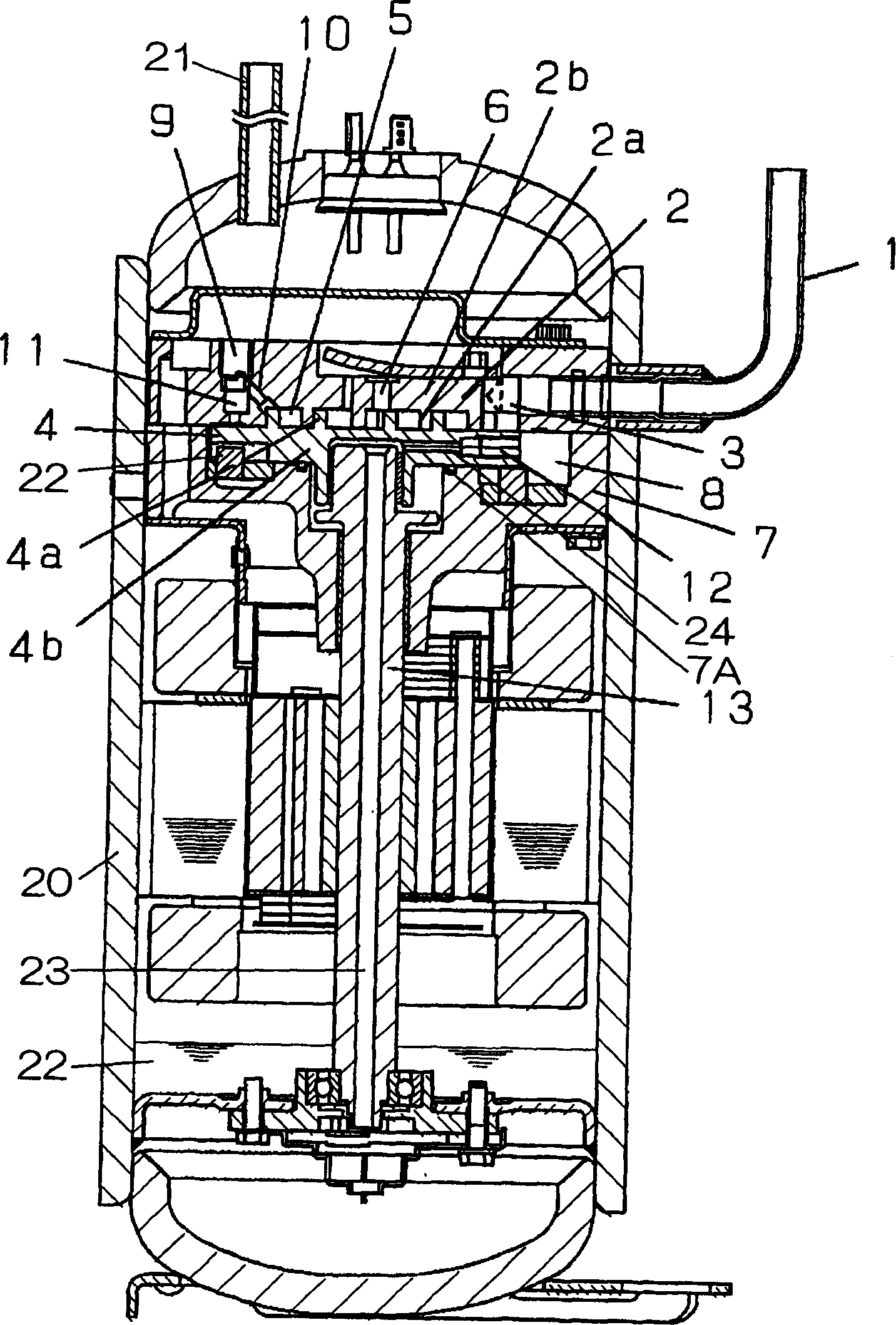
[0034] figure 1 The scroll compressor of the first embodiment is shown.

[0035] The scroll compressor has a compression mechanism part and a motor mechanism part in the airtight container 20 . The compression mechanism unit is disposed above the airtight container 20 , and the motor mechanism unit is disposed below the compression mechanism unit. A suction pipe 1 and a discharge pipe 21 are provided on the upper portion of the airtight container 20 . An oil storage portion 22 for storing lubricating oil is provided at a lower portion inside the airtight container 20 .

[0036] In the compression mechanism part, the fixed scroll 2 and the orbiting scroll 4 form a compression chamber 5 composed of a plurality of compression spaces. The fixed scroll member 2 is constituted by erecting a wrap 2a from an end plate 2b, and the orbiting scroll member 4 is constituted by erecting a wrap 4a from an end plate 4b. The compression chamber 5 is formed by engaging the wrap 2a and the ...


PUM


Abstract

According to a scroll compressor of the present invention, lubricant is supplied to a compression chamber in the proportions of 2% by weight or more and less than 20% by weight of the lubricant to the sucked refrigerant amount. With this, it is possible to provide an efficient scroll compressor even when carbon dioxide is used as the refrigerant.

Description

technical field [0001] The present invention relates to a scroll compressor, which forms a compression chamber by meshing a wrap of a fixed scroll member and a wrap of a revolving scroll member, and constrains the rotation of the revolving scroll member so that it moves along a circle. The orbit rotates, and the compression chamber formed between the wrap of the fixed scroll and the wrap of the orbiting scroll moves while changing volume to discharge the sucked refrigerant. Background technique [0002] In the field of refrigerating and air-conditioning for home use and business use, reciprocating compressors, rotary compressors, and scroll compressors are used as hermetic compressors for refrigerating and air-conditioning. These reciprocating compressors, rotary compressors, and scroll compressors have been developed by making use of their respective characteristics in terms of cost and performance. [0003] For the purpose of soundproofing and easy maintenance, a hermetic...

Claims


Application Information

Patent Timeline
Patent Type & Authority Applications(China)
IPC IPC(8): F04C18/02F04C29/00F04C29/02
CPCF04C18/0215F04C2210/1072F04C2210/261F04C2210/1027F04C2210/14F04C29/0007F04C2210/142F04C29/028F04C2210/145F04C18/02
Inventor 鶸田晃二上義幸飯田登澤井清
Owner PANASONIC CORP
Why Eureka
Try Eureka