
A piston rod seal assembly for a hot air engine

A technology for sealing components and piston rods, which is used in the sealing of engines, hot gas variable capacity engine devices, engine components, etc., can solve problems such as easy oil leakage, poor reliability, and working fluid pollution, and achieve pollution prevention and good results. Effect

Active Publication Date: 2019-08-02
SHANGHAI MICROPOWERS
View PDF3 Cites 0 Cited by
  • Summary
  • Abstract
  • Description
  • Claims
  • Application Information

AI Technical Summary

Problems solved by technology

[0003] The technical problem to be solved by the present invention is to provide a piston rod sealing assembly for a heat engine, which solves the problems that the current piston rod sealing assembly is prone to oil leakage, the working medium is easily polluted, and has poor reliability. Features of simplicity and high reliability

Method used


Image

  • A piston rod seal assembly for a hot air engine

Examples


Embodiment Construction

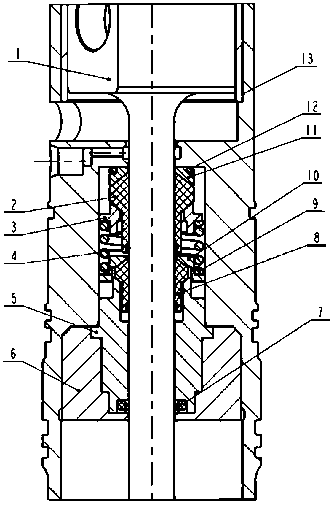
[0015] like figure 1 As shown, the piston rod seal assembly for a hot air engine is composed of a cap seal 7 sleeved on the piston rod 1, a main seal assembly, an auxiliary main seal assembly and a gland 6. The main seal assembly consists of a conical seat 11, The main seal 2, the main seal gland 3 and the spring 9 are composed. The auxiliary main seal assembly is arranged between the main seal assembly and the cap seal 7. The auxiliary main seal assembly consists of the auxiliary main seal 8, the auxiliary main seal gland 10 and the spring 9. The structure of the auxiliary main seal 8 is similar to that of the main seal 2. It is a rod seal sleeved on the piston rod 1, and its outer side is provided with two upper and lower conical bosses. The lower end of the boss is against the conical surface. On the corresponding conical surface boss of the spring seat 5 , the upper conical surface of the boss is pressed by the corresponding conical surface boss of the auxiliary main seali...


PUM


Abstract

The invention discloses a piston rod sealing assembly for a hot-air engine. The assembly comprises a cap type seal arranged on a piston rod in a sleeving mode and a main sealing assembly, wherein the main sealing assembly is composed of a conical base, a main seal, a main seal gland and a spring; an auxiliary sealing assembly is further arranged between the main sealing assembly and the cap type seal and is composed of an auxiliary main seal, an auxiliary main seal gland and a spring, the auxiliary main seal is a rod sealing piece arranged on the piston rod in a sleeving mode, an upper conical face boss and a lower conical face boss are arranged on the outer side of the auxiliary main seal, the lower end conical face of each auxiliary main seal boss abuts against a corresponding conical face boss of a spring base, the upper end conical face of each auxiliary main seal boss is pressed by a corresponding conical face boss of the auxiliary main seal gland, and the upper end of the auxiliary main seal gland is tightly pressed by the spring. The piston rod sealing assembly has the advantages of being compact in structure and good in sealing effect and is particularly suitable for the application occasion where a solar operated hot-air engine and the like need to run in a front-stand state or in an inverted state.

Description

technical field [0001] The invention relates to the field of engines, in particular to a piston rod sealing device for a heat engine. Background technique [0002] A heat engine is an external combustion engine that heats the working medium in a closed cycle through the heat generated by external combustion or a heat source. When the Stirling engine works, the working medium gas does work in a closed cycle inside the heat engine. In order to improve the performance and reliability of the engine, prevent the leakage and contamination of the working fluid, and improve the sealing effect of the working fluid system, it is particularly important to improve the sealing effect of the piston rod. The Chinese invention patent publication number CN200312345 discloses a non-oil lubricated piston-type gas compressor piston rod oil-proof sealing structure. The sealing structure is composed of a self-tightening cap-type seal and a rod-type seal. A lower seal seat, a rod seal abutting ag...

Claims


Application Information

Patent Timeline
Patent Type & Authority Patents(China)
IPC IPC(8): F02G1/053
CPCF02G1/0535F02G2253/03
Inventor 朱辰元凌虹轩连
Owner SHANGHAI MICROPOWERS
Learn More