Sealing device for oil sealing and sand removal

A sealing device and oil-sealing technology, which is applied in the direction of supporting elements of blades, machines/engines, and leakage prevention, can solve problems such as oil leakage in bearing chambers, wear of impeller shafts and bushings, and reduction of mechanism reliability and service life. Achieve the effect of solving the wear problem, highly reliable sealing performance, improving reliability and service life

Active Publication Date: 2022-03-25
AECC HUNAN AVIATION POWERPLANT RES INST
View PDF5 Cites 0 Cited by
  • Summary
  • Abstract
  • Description
  • Claims
  • Application Information

AI Technical Summary

Problems solved by technology

[0003] The present invention provides a sealing device for oil sealing and sand removal to solve the problem of oil leakage in the bearing cavity of the power transmission mechanism, and the accumulated foreign matter causes wear of the high-speed rotating impeller shaft and bushing, which reduces the reliability and use of the entire mechanism. technical issues of longevity

Method used


Image

  • Sealing device for oil sealing and sand removal
  • Sealing device for oil sealing and sand removal
  • Sealing device for oil sealing and sand removal

Examples


Embodiment Construction

[0028] It should be noted that, in the case of no conflict, the embodiments in the present application and the features in the embodiments can be combined with each other. The present invention will be described in detail below with reference to the accompanying drawings and examples.

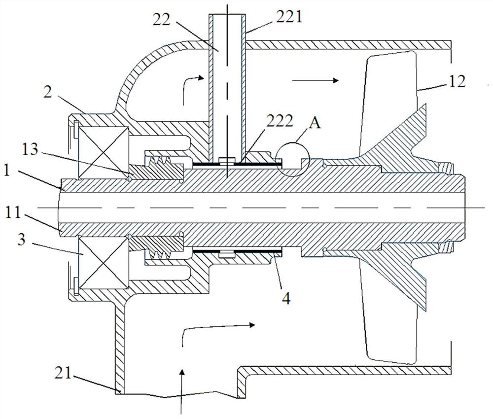
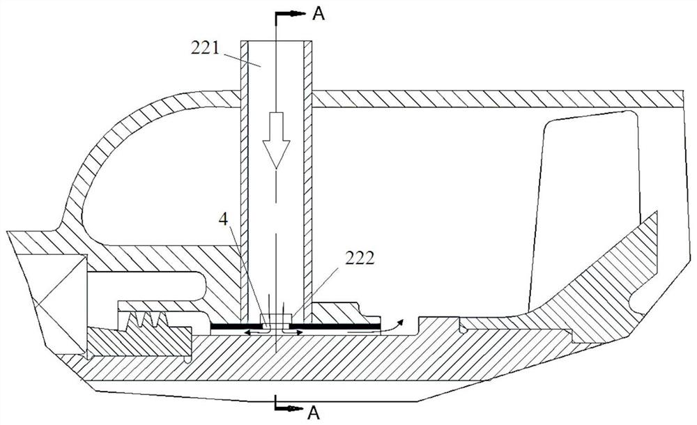
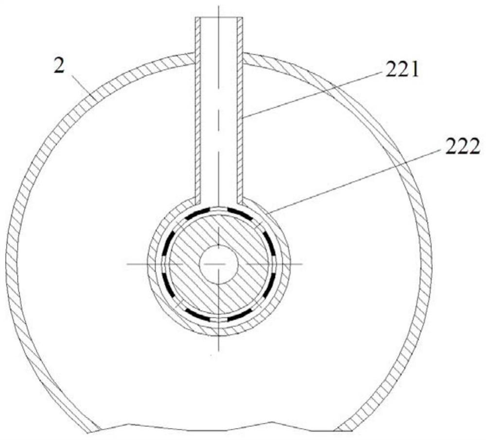
[0029] figure 1 It is a schematic diagram of a sealing device for oil sealing and sand discharge in a preferred embodiment of the present invention; figure 2 It is a diagram of the external air circulation path of the sealing device for oil sealing and sand discharge in the preferred embodiment of the present invention; image 3 It is the A-A diagram for oil sealing and sand discharge of the preferred embodiment of the present invention.

[0030] Such as figure 1 and figure 2 As shown, the sealing device for oil sealing and sand discharge in this embodiment includes: an impeller shaft assembly 1 for power transmission; a casing 2 for accommodating the impeller shaft assembly 1 and support...


PUM


Abstract

The invention discloses a sealing device for oil sealing and sand discharge, comprising: an impeller shaft assembly for power transmission; a casing for accommodating the impeller shaft assembly and supporting the impeller shaft assembly through a bearing; At the power input end, the bearing, the impeller shaft assembly and the casing are enclosed to form a bearing cavity; the casing is provided with an air inlet mechanism for the outside air to enter, and there is a device surrounding the impeller shaft assembly between the impeller shaft assembly and the casing. As the bushing supporting the air inlet mechanism, the bushing fits with the impeller shaft assembly in a gap, the outside air is introduced through the air inlet mechanism and passes through the bushing into the gap between the bushing and the impeller shaft assembly, and part of the air flow flows to the bearing cavity. Another part of the airflow flows to the power take-off of the impeller shaft assembly. The sealing device for oil sealing and sand discharge of the present invention flows into the gap between the bushing and the impeller shaft assembly through the air inlet mechanism and flows to both ends of the bushing, so as to seal the oil in the bearing cavity and remove foreign matter. role.

Description

technical field [0001] The invention relates to the field of aviation turboshaft engines, in particular to a sealing device for sealing oil and discharging sand. Background technique [0002] In the existing power transmission mechanism of an aero turboshaft engine, the impeller is often supported by a single bearing cantilever due to structural limitations, and a gearbox is used to drive the impeller shaft to rotate. In the current drive shaft structure, due to the inevitable deflection and deformation of the impeller shaft of the cantilever during the working process, errors in the manufacturing and assembly process, and wear of various components after long-term use, the rotation accuracy of the impeller shaft is reduced, which brings Vibration problem, its vibration effect will be transmitted to the casing, affecting the stability of the mechanism. Usually, a bush is used to protect the impeller shaft, so that the cantilever impeller shaft can obtain a relatively stable...

Claims


Application Information

Patent Timeline
Patent Type & Authority Patents(China)
IPC IPC(8): F01D11/00F01D5/02F01D25/00
CPCF01D11/00F01D5/02F01D25/002
Inventor 陈冰鄢骏周七二徐大成李攀
Owner AECC HUNAN AVIATION POWERPLANT RES INST
Why Eureka
Try Eureka