
Single-drive multi-cylinder compressor structure

A compressor, single-drive technology, applied in the direction of machine/engine, multi-stage pump, mechanical equipment, etc., can solve the problems of low working efficiency of the compressor structure, large wear of the piston pin, affecting the service life of the compressor, etc. The effect of high pin wear, long service life and high use value

Active Publication Date: 2012-11-14
HANGZHOU QIANJIANG REFRIGERATION COMPRESSOR GRP CO LTD
View PDF8 Cites 11 Cited by
  • Summary
  • Abstract
  • Description
  • Claims
  • Application Information

AI Technical Summary

Problems solved by technology

[0003] The purpose of the present invention is to provide a high-efficiency single-drive multi-cylinder compressor structure for solving the problem of low working efficiency of the compressor structure in the prior art
[0005] The third object of the present invention is to provide a single-drive multi-cylinder compressor with less wear and tear on piston pins and long compressor life in order to solve the problem that the piston pins of the compressor structure in the prior art wear heavily and affect the service life of the compressor. Compressor structure

Method used


Image

  • Single-drive multi-cylinder compressor structure
  • Single-drive multi-cylinder compressor structure
  • Single-drive multi-cylinder compressor structure

Examples


Embodiment 1

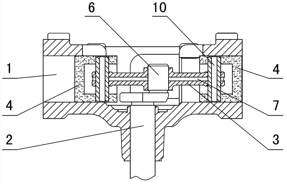
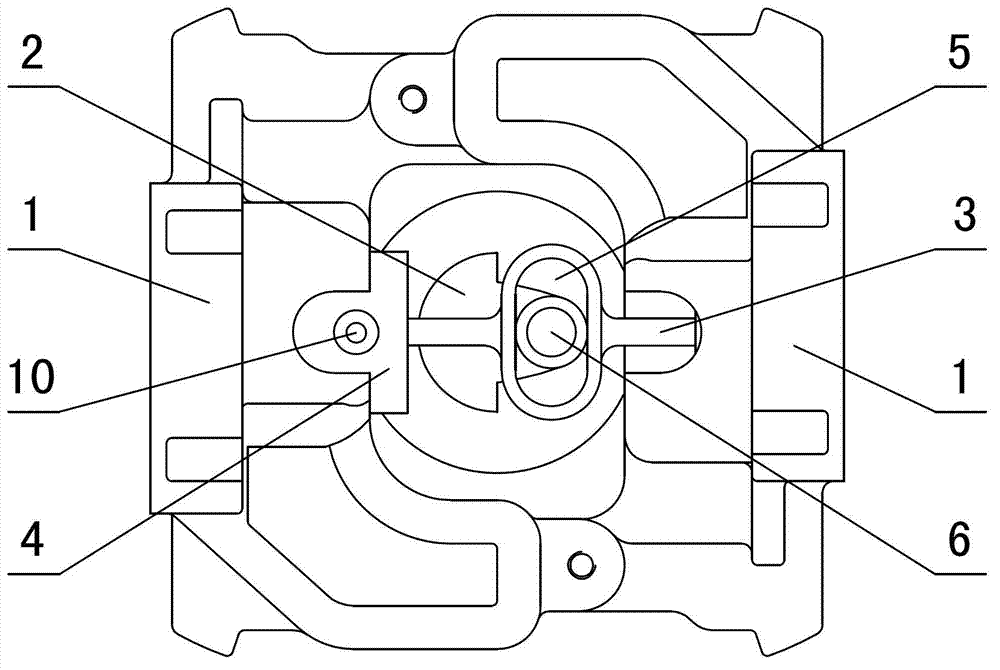
[0030] in such as figure 1 figure 2 In the shown embodiment 1, a single-drive multi-cylinder compressor structure includes a crankshaft and a cylinder arranged in the radial direction of the crankshaft and driven by the crankshaft. There are two cylinders, and the piston holes 1 of the two cylinders are symmetrical. Set on both sides of the crankshaft 2, the central axes of the two cylinders are on the same plane as the central axis of the crankshaft. The crankshaft is provided with a crank throw 6, and the crankshaft passes through an inline three-hole connecting rod 3 (see Figure 5 Figure 6 ) is connected with the pistons 4 of the two cylinders, the three-hole connecting rod is a homogeneous center-symmetrical structure, the center of the three-hole connecting rod is provided with a chute 5 perpendicular to the length direction of the three-hole connecting rod, and the three-hole connecting rod The two piston pin holes 8 are arranged symmetrically on both sides of the c...

Embodiment 2

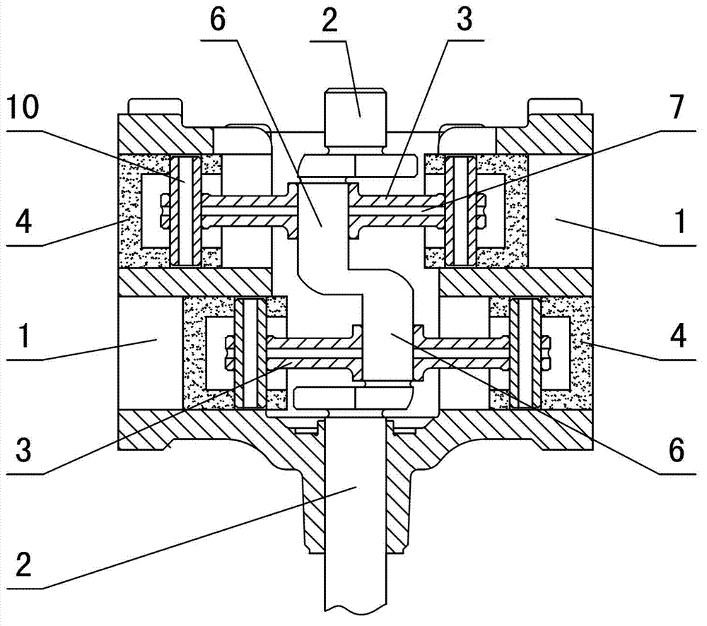
[0032] in such as image 3 In the shown embodiment 2, there are four cylinders, and the central axes of the four cylinders are on the same plane as the central axis of the crankshaft. The piston holes of the cylinders are divided into two pairs and arranged symmetrically on both sides of the crankshaft. There are two crank throws arranged in dislocation on both sides, and the two crank throws are connected to the pistons on both sides of the crankshaft through two three-hole connecting rods. The three-hole connecting rods are segmented structures, that is, the three-hole connecting rods are composed of The two-section connecting rod body is screwed together (see Figure 7 ), the chute in the middle of the three-hole connecting rod is formed by closing two opposite openings, so that the three-hole connecting rod can be conveniently set on the crank throw. The phase difference between the piston movements of the two cylinders on the same side of the crankshaft is 180 degrees. T...

Embodiment 3

[0034] There are four cylinders in embodiment 3, the central axes of the four cylinders and the central axis of the crankshaft are on the same plane, and the piston holes of the cylinders are divided into two pairs and symmetrically arranged on both sides of the crankshaft. Two bellcranks arranged in dislocation, the two bellcranks are connected to the pistons on both sides of the crankshaft through two three-hole connecting rods. The three-hole connecting rods are segmented structures, that is: the three-hole connecting rods body screw connection (see Figure 7 ), the chute in the middle of the three-hole connecting rod is formed by closing two opposite openings, so that the three-hole connecting rod can be conveniently set on the crank throw. The phase difference between the piston movements of the two cylinders on the same side of the crankshaft is 180 degrees, and each of the four cylinders is provided with an air outlet branch pipe, and the rest are the same as in Embodim...


PUM


Abstract

The invention discloses a single-drive multi-cylinder compressor structure. The structure comprises a crank shaft and cylinders, wherein the cylinders are arranged on the radial direction of the crank shaft and are driven by the crank shaft, the number of the cylinders is even, the cylinders are arranged on two opposite sides of the crank shaft in pairs, the central axis of the same pair of cylinders and the central axis of the crank shaft are arranged in the same plane, the crank shaft is connected with pistons which are arranged on the same pairs of cylinders through a linear three-hole connecting rod, a chute which is vertical to the three-hole connecting rod is arranged in the center of the three-hole connecting rod, and the crank shaft is connected with the interior of the chute in a sliding mode. By the aid of the compressor structure, problems that in existing refrigerating compressors of the prior art, working efficiency is low, the vibration is large, the noise pollution is serious, piston pins are abraded and the service life is short are solved. The compressor structure has the advantages of being stable in operation, low in noise and long in service life. The compressor structure has high usage value and is suitable to various compressors.

Description

technical field [0001] The invention relates to a structure of a compressor, in particular to a structure of a single-drive multi-cylinder compressor. Background technique [0002] At present, among electrical equipment using compressors, single-cylinder compressors with relatively simple structure and low cost are widely used. However, there are also many defects in the single-cylinder compressor. First, the crankshaft rotates once, and the compressor only does work once, so the working efficiency of the compressor is low; secondly, because the structure of the single-cylinder compressor is asymmetrical, the compressor The vibration during the working process is relatively large, and there is relatively large noise pollution. For household appliances such as refrigerators and freezers, relatively large noise will seriously affect people's lives and is a major product defect. In addition, in the prior art, the connection between the connecting rod and the piston of the comp...

Claims


Application Information

Patent Timeline
Patent Type & Authority Applications(China)
IPC IPC(8): F04B27/02F04B39/00
Inventor 高骐高尔发
Owner HANGZHOU QIANJIANG REFRIGERATION COMPRESSOR GRP CO LTD
Learn More