Coin changing device

A coin and coin box technology, which is applied in the direction of handling coins or valuable banknotes, coin finding machines, instruments, etc., to prevent unreasonable contact with coins

Inactive Publication Date: 2004-08-11
SHANGHAI HUAHONG JITONG SMART SYST
View PDF0 Cites 2 Cited by
  • Summary
  • Abstract
  • Description
  • Claims
  • Application Information

AI Technical Summary

Problems solved by technology

[0003] The invention provides a coin change device, aiming to so

Method used


Image

  • Coin changing device
  • Coin changing device
  • Coin changing device

Examples


Embodiment Construction

[0012] The present invention is described in detail below in conjunction with accompanying drawing:

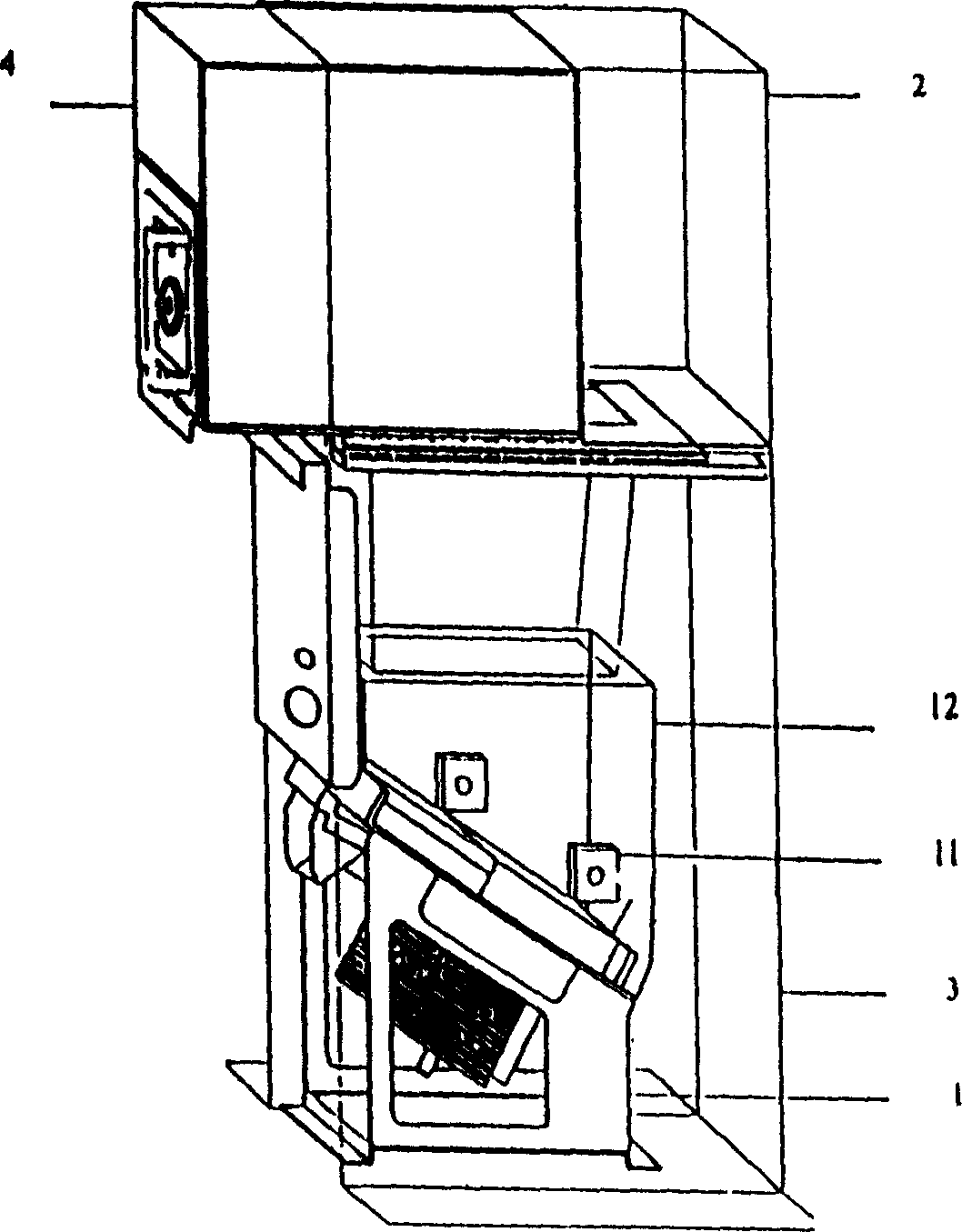
[0013] Such as figure 1 As shown: the device includes an electric mechanical change machine 1, a photoelectric sensor 11, a coin box 12, a lower end of the change rack box 3, an upper end of the change rack box 2, a coin replenishment box 4, and the lower end of the change rack box 3 to cover the electric mechanical change machine 1, the coin replenishment box 4 is disassembled and connected to the upper end 2 of the change rack box, and the upper end 2 of the change rack box is fixedly connected to the lower end 3 of the change rack box.

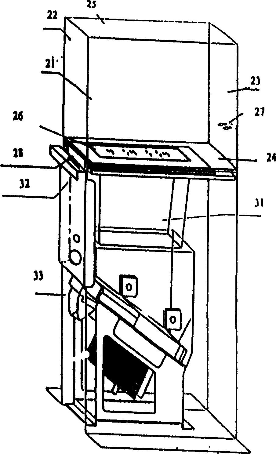
[0014] Such as figure 2 As shown, the upper end 2 of the change rack box has a front plate 21, a rear plate 22, a right plate 23, a bottom plate 24, and a top plate 25 fixedly connected in sequence.

[0015] The bottom plate 24 at the upper end of the change rack box has a first opening 26, and the first opening 26 is fixedly connected w...


PUM


Abstract

The device includes electric mechanical coin-changing device, photoelectric sensor, coin receptacle, lower end of stand box, upper end of stand box, and coin supply box. The said lower end of stand box covers the electric mechanical coin-changing device. The coin supply box is connected to upper end of stand box through disassembling procedure. The upper end of stand box is connected to the lower end of stand box fixedly. The invention ensures safety to supply coins to the device, preventing operating personnel from contacting coins unreasonably so as to block up loophole in management. The invention is applicable to automatic ticketing system in station of city track transportation.

Description

technical field [0001] An automatic ticket vending system, especially a coin changing device. Background technique [0002] In the automatic ticket vending system (abbreviated ATVM) of urban rail transit stations, automatic ticket vending is an important component. In the process of selling tickets with banknotes, the ATVM must have an automatic change function for coins. After frequent change, the change machine must be replenished with coins in time. Operators were able to access coins during coin replenishment, causing administrative confusion. Contents of the invention [0003] The invention provides a coin changing device, aiming to solve the management problem in the coin replenishment process. [0004] In order to solve the above-mentioned technical problems, the technical solution of the present invention is: comprise electromechanical change machine, photoelectric sensor, coin box, change rack box lower end, change rack box upper end, coin replenishment box, de...

Claims


Application Information

Patent Timeline
IPC IPC(8): G07D1/02G07D1/06
Inventor 王融立
Owner SHANGHAI HUAHONG JITONG SMART SYST
Why Eureka
Try Eureka