Method for identifying image space resolution of CT unit by CT unit bearing gap

A technology of image space and bearing clearance, applied in the field of medical equipment, can solve problems such as inconvenient diagnosis, affecting image effect, and complex mechanical structure

Inactive Publication Date: 2005-01-12
PHILIPS CHINA INVESTMENT +1
View PDF0 Cites 7 Cited by
  • Summary
  • Abstract
  • Description
  • Claims
  • Application Information

AI Technical Summary

Problems solved by technology

[0003] At present, due to the complex mechanical structure and precision errors of CT machines, the center of rotation and the center of gravity of the machine are offset, and sometimes even exceed the allowable limit of the machine. As a result, the spatial resolution of the CT image is reduced, which seriously affects the image effect. Accurate diagnosis is inconvenient

Method used


Image

  • Method for identifying image space resolution of CT unit by CT unit bearing gap
  • Method for identifying image space resolution of CT unit by CT unit bearing gap
  • Method for identifying image space resolution of CT unit by CT unit bearing gap

Examples


Embodiment Construction

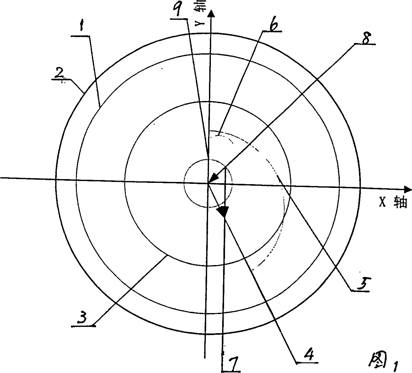
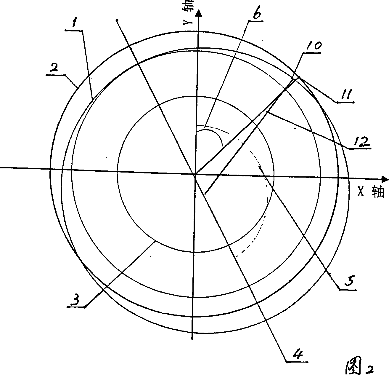
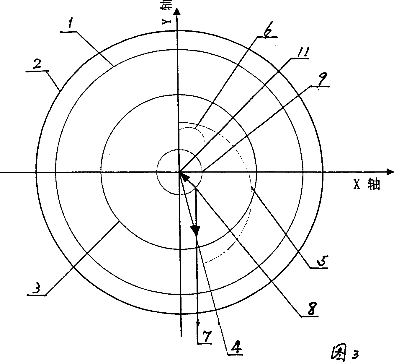
[0070] The invention discloses a method for judging the spatial resolution of a CT machine image through the CT machine bearing clearance, which is described in combination with embodiments.

[0071] Step 1: Input the imaging field of view (fov), offset angle (angle), rotation speed (speed), and bearing clearance (offset) parameters in the option-setting fov dialog box of the program execution interface;

[0072] Step 2: Click option-Modelspace on the program execution interface to generate image model data;

[0073] Step 3: Click option-Reconstruct on the program execution interface to reconstruct the image;

[0074] Step 4: Observe the created image to see how much resolution it can achieve.

[0075] Constantly change the offset and parameters of the model in step 1 to see the image effect, and refer to the attached picture for image comparison. From these test data, a certain basis can be provided for the design or selection of mechanical bearings.

[0076] in:

[0077] ...


PUM


Abstract

A method for judging the resolution in image space of CT machine by the bearing gap of CT machine includes creating the geometric model of bearing shifting direction caused by gravitational center shift of CT machine, calculating the shift of rotational center by use of the bearing gap, finding out the shift of central coordinate, inputting it to computer, calculating the data about image, rendering the image, and comparing it with standard one.

Description

technical field [0001] The invention relates to the technical field of medical equipment, in particular to a method for discriminating spatial resolution in a CT machine. Background technique [0002] The bearing used in the spiral CT machine is composed of two concentric circles inside and outside, with balls embedded in the middle, and the balls are not tightly attached to the inner and outer walls of the bearing, but there is a certain gap, we call it the bearing gap. To indicate that it is precisely because of the existence of this gap that the inner and outer walls of the bearing move and squeeze, causing the bearing to shift the center of rotation in different directions. The size of the shift is equal to the bearing gap, which is constantly changing randomly. In theory, the spiral The center of rotation of the CT machine and the center of gravity of the entire machine should be the same point, but due to various mechanical reasons, this requirement is difficult to ach...

Claims


Application Information

Patent Timeline
Patent Type & Authority Applications(China)
IPC IPC(8): A61B6/03
Inventor 李双学楼珊珊刘晋军佟丽霞
Owner PHILIPS CHINA INVESTMENT
Why Eureka
Try Eureka