Closing device for electric box

A technology of closing device and connecting device, applied in substation/switch layout details, electrical components, chassis/cabinet/drawer parts, etc.

Active Publication Date: 2005-03-23
SCHNEIDER ELECTRIC IND SAS
View PDF2 Cites 9 Cited by
  • Summary
  • Abstract
  • Description
  • Claims
  • Application Information

AI Technical Summary

Problems solved by technology

[0003] The known boxes have the disadvantage that they need to be arranged differently depending on whether the cover is fixed to the casing by means of a quarter-turned locking element or by screws cooperating with nuts, since in the second case the required Nut while in the first case there is no need to use a nut

Method used


Image

  • Closing device for electric box
  • Closing device for electric box
  • Closing device for electric box

Examples


Embodiment Construction

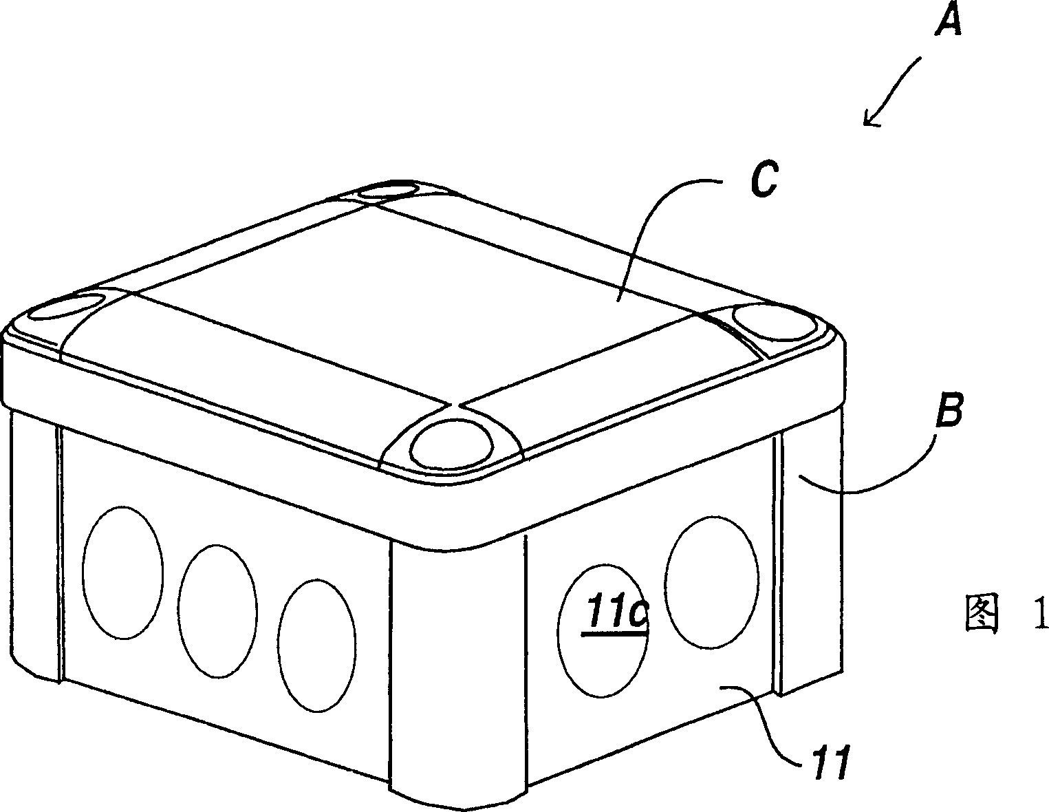
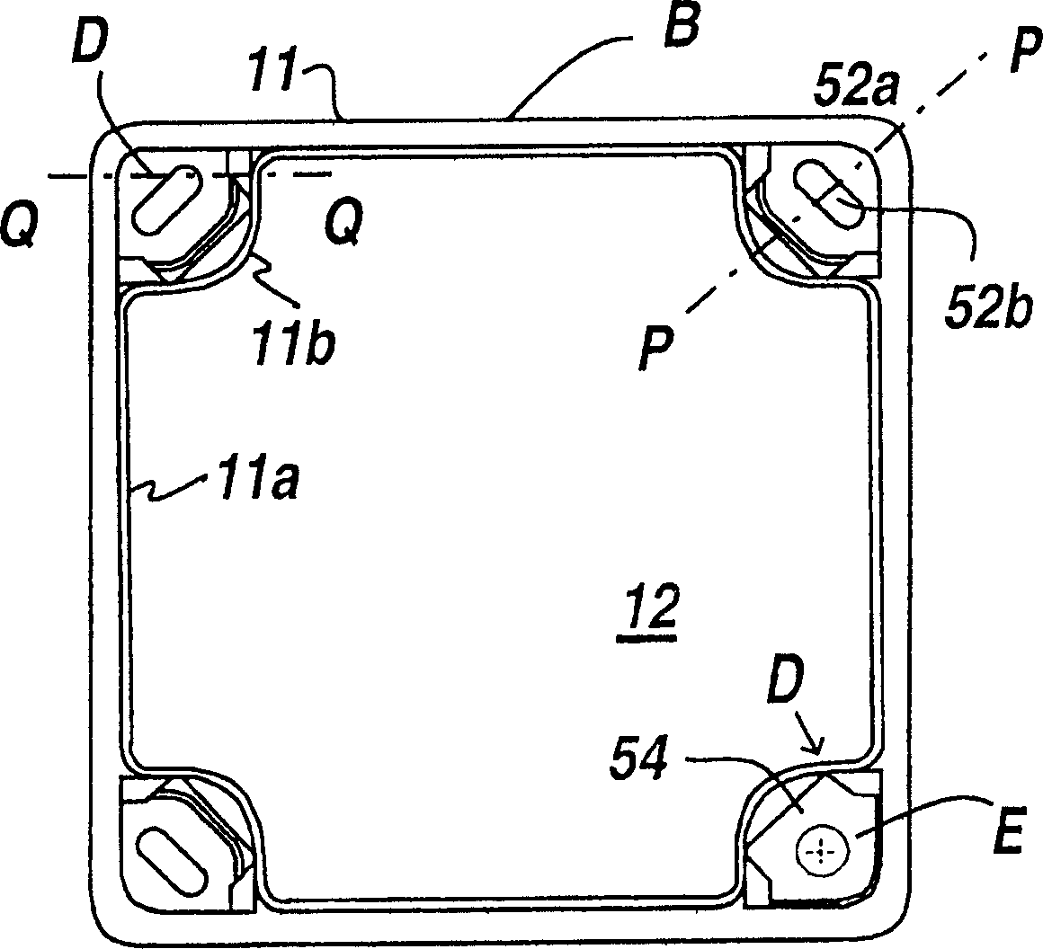
[0023] Box A shown in the figure is an industrial box, junction box, enclosure or other similar housing designed to house electrical devices or components. The box, generally quadrilateral, includes a casing B and a cover C made of insulating material. The housing B has a bottom wall 10 defining an interior space 12 intended to accommodate electrical components, and a side wall 11 defining a peripheral neck 11a opposite the bottom wall 10, on which a cover C is fixed and sealed Above, the walls 11 are connected to each other at the corners by means of concave corner walls 11 b forming a volume dedicated to oriented isolated ducts outside the space 12 traversing the bottom wall 10 . Openings 11c are also provided in the wall 11 to accommodate cut-off or push switches, thereby allowing cables to pass through these holes.

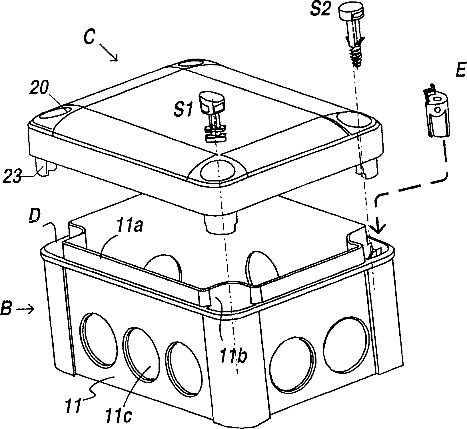
[0024] The quadrilateral cover C is fastened to the housing B via a quarter-turn connection S1 or a threaded screw-type connection element S2. The cover C i...


PUM


Abstract

The invention relates to a closing device for a shell, in particular to an industrial box or a terminal box, wherein, the invention comprises a shell which takes a quadrangular shape basically and a cover assembled on the shell. The cover is assembled on the shell through a connection device connected with the cover and included in a pipeline which is arranged on an angle of the shell. The angle pipeline (D) is provided with a clapboard (51) for limiting a main cavity (52). If necessary, a quarter turning unit (S1) or a threaded screw connection device (S2) can be assembled inside the main cavity (52). The clapboard (51) is provided with a locking bottom (32) for holding the quarter turning unit and an opening (53) for locking a transverse-held convex edge positioned at the locking bottom.

Description

technical field [0001] The invention relates to a closing device for housings made of insulating material, in particular for industrial boxes or junction boxes for electrical components. Background technique [0002] Boxes of this type are commonly used on the market and comprise, for example, a generally prismatic housing comprising a bottom wall and side walls delimiting a space intended to house electrical components, in particular wiring, connectors, switching elements, etc. space. A detachable cover is added on the shell to close the defined space, and the cover is assembled on the shell through connecting devices received in corresponding pipes arranged on the corners of the cover and the shell. Cassettes of this type are described in documents US4632269 and DE7904441U. [0003] The known boxes have the disadvantage that they need to be arranged differently depending on whether the cover is fixed to the casing by means of a quarter-turned locking element or by screws...

Claims


Application Information

Patent Timeline
IPC IPC(8): H02B1/46
CPCH02B1/46H02G3/086H02G3/14
Inventor 伊曼纽尔·布伊特伯纳德·布奇皮埃尔·拉斯基
Owner SCHNEIDER ELECTRIC IND SAS
Why Eureka
Try Eureka