Separation device of storehouse type powdered coal boiler powder making system powder sending air laeking

A technology of pulverized coal boiler and separation device, which is applied in the directions of block/powder supply/distribution, combustion using block fuel and powder fuel, combustion method, etc., can solve problems such as high cost and difficult separation, and achieve simple structure. Effect

Inactive Publication Date: 2005-06-08
TSINGHUA UNIV
View PDF0 Cites 13 Cited by
  • Summary
  • Abstract
  • Description
  • Claims
  • Application Information

AI Technical Summary

Problems solved by technology

[0004] Aiming at the deficiencies and defects of the prior art, the purpose of the present invention is to propose a new separation device for hot air or warm air powder delivery exhaust gas in the storage powder making s

Method used


Image

  • Separation device of storehouse type powdered coal boiler powder making system powder sending air laeking
  • Separation device of storehouse type powdered coal boiler powder making system powder sending air laeking
  • Separation device of storehouse type powdered coal boiler powder making system powder sending air laeking

Examples


Embodiment Construction

[0011] The specific structure, principle and working process of the present invention will be further described below in conjunction with the accompanying drawings and embodiments.

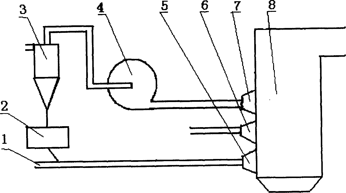
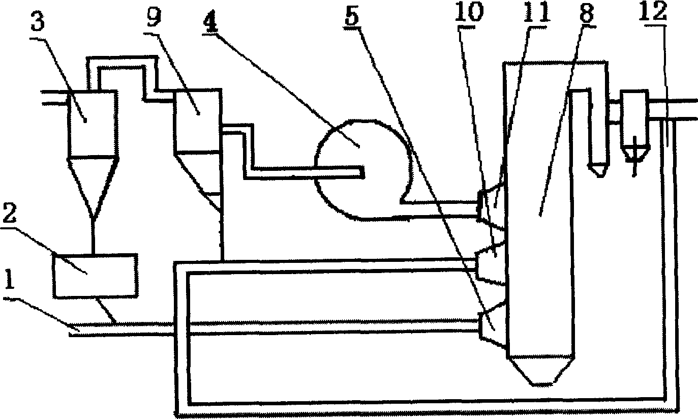
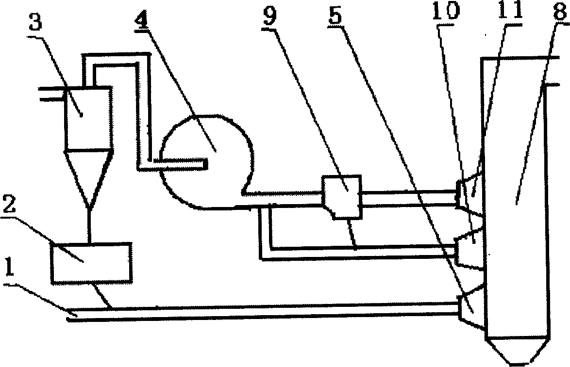
[0012] Figure 4 Schematic diagram of the structure of the separation device for powder feeding and exhaust gas in the pulverization system of the storage type pulverized coal boiler provided by the present invention. It includes a fine powder separator 3, a powder discharge fan 4 connected with the gas outlet of the fine powder separator, a coal powder bin 2 arranged at the lower part of the fine powder separator, and a primary air duct 1 connected with the coal powder bin. When the pulverized coal contained in the exhaust gas from the fine powder separator 3 flows through the impeller of the powder exhaust fan 4 rotating at high speed, due to the centrifugal force, the concentration distribution of the airflow containing pulverized coal at the outlet of the fan is no longer uniform , Separation...


PUM


Abstract

A storage pulverized-fuel boiler powder making system, which uses disequilibrium of the beta distribution of the breeze to divide the dead steam into two parts, which are thick and thin. They are caught into the furnace cavity through the wind ejector nozzle once and twice. It is simple, which doesn't need the collector.

Description

technical field [0001] The invention relates to a separation device for hot air or warm air powder feeding exhaust air in a storage pulverization system, and belongs to the technical field of storage pulverized coal boiler pulverization system and combustion. Background technique [0002] At present, storage-type pulverized coal boilers are widely used in coal-fired power plants in my country. The structure of this boiler pulverization system is as follows: figure 1 As shown, in this system, the exhaust gas from the fine powder separator 3 contains about 10% to 20% coal powder, so this part of exhaust gas is generally sent into the boiler furnace 8 through the tertiary air nozzle 7 as tertiary air However, when low-quality coal is used as fuel, this kind of boiler often has problems such as high carbon content in fly ash and high NOx emissions, which is inconsistent with my country's current environmental protection policy, so it is necessary to transform this pulverizing sys...

Claims


Application Information

Patent Timeline
IPC IPC(8): F23C1/06F23C7/00F23K3/02
Inventor 吕俊复李建锋张海张建胜刘青岳光溪
Owner TSINGHUA UNIV
Why Eureka
Try Eureka