Timepiece with an hour hand able to be moved forward or backward by one hour step

A technology of clocks and hour hands, applied in the direction of mechanically driven clocks, clocks, time-indicating mechanisms, etc.

Active Publication Date: 2005-06-22
OMEGA SA
View PDF2 Cites 3 Cited by
  • Summary
  • Abstract
  • Description
  • Claims
  • Application Information

AI Technical Summary

Problems solved by technology

To the applicant's knowledge, this problem has not been resolved to date, which is why no time zone w

Method used


Image

  • Timepiece with an hour hand able to be moved forward or backward by one hour step
  • Timepiece with an hour hand able to be moved forward or backward by one hour step
  • Timepiece with an hour hand able to be moved forward or backward by one hour step

Examples


Embodiment Construction

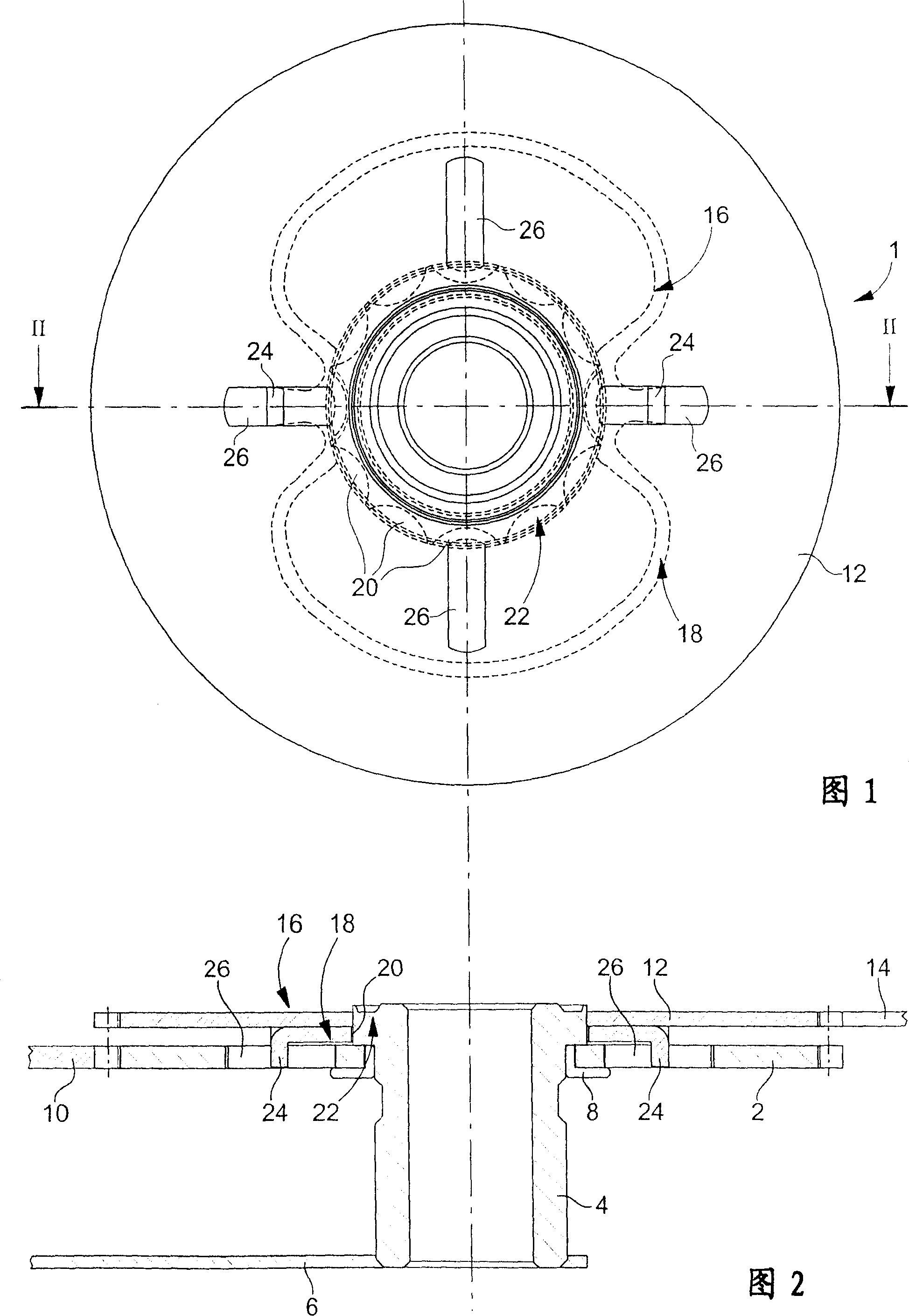
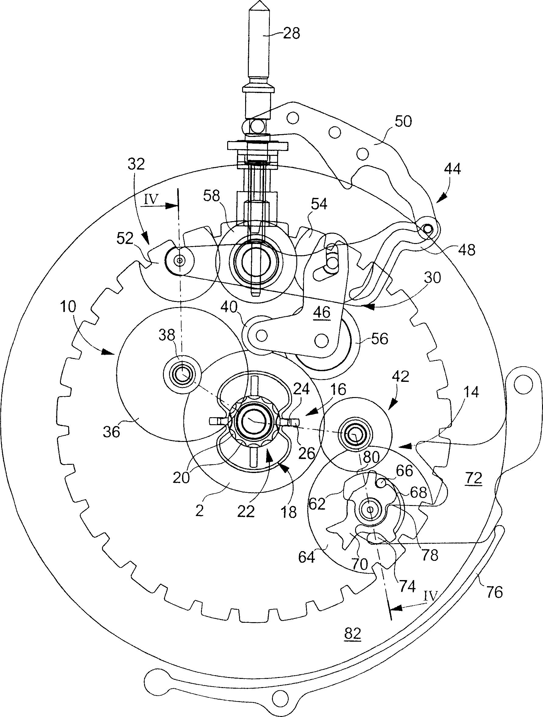
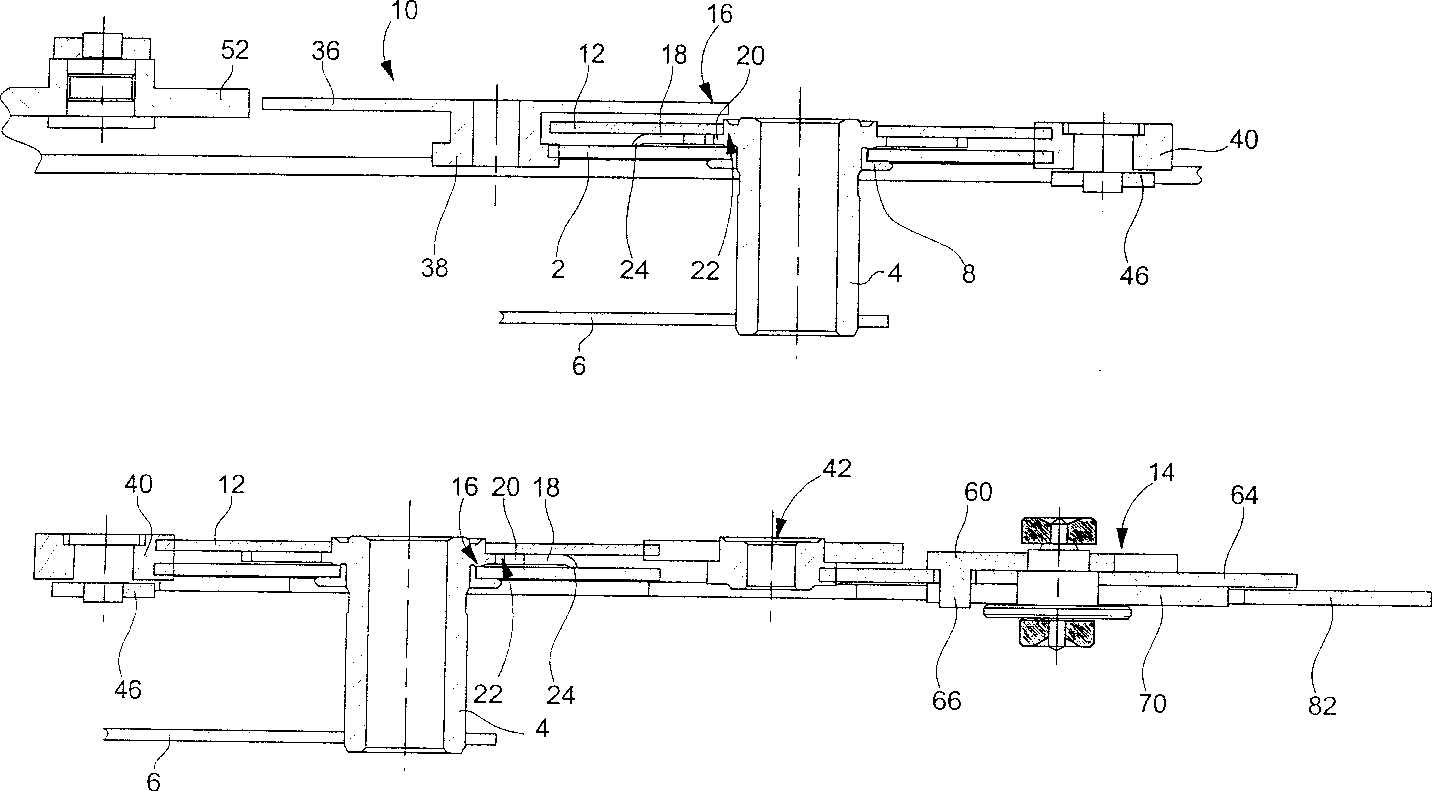
[0021] The present invention arises from the general inventive idea of ​​rigidly engaging the hour wheel with the additional wheel by means of a connecting pinion in all operating phases of the time zone timepiece, except the time in the regulation zone. Thus, the torque transmission from the motion work to the additional device is transmitted through the hour wheel, the connecting pinion and the additional wheel during the working phase and the time-setting phase. The transmission of the force between the hour wheel and the additional wheel is thus deviated (original path) through the connecting pinion, with the exception of the time in the set zone - in which case the connecting pinion is disengaged - making the time The limited torque mechanism where the wheel and the additional wheel are engaged is no longer in operation.

[0022] The present invention will be described below in conjunction with an additional device of the instantaneous calendar mechanism type. Of course ...


PUM


Abstract

The timepiece has a hand fitted onto an hour pipe, about which an hour hand is adjusted to freely pivot by a motion work. An additional wheel (12) secured to the pipe, drives an additional device. An hour wheel (2) is rigidly coupled to the additional wheel by a limiting torque mechanism and a coupling mechanism. A spring is immobilized and compressed in a space between two teeth of a star wheel.

Description

technical field [0001] The present invention relates to a time zone timepiece, the hour hand of which can be moved forward or backward in one-hour steps by means of a manual time setting handle without affecting the display of minutes. technical background [0002] A timepiece of the above type is very useful when a traveler travels from one time zone to another and has to adjust his watch to the new time. Because the difference between the new time and the old time is a full hour in one direction or the other, it would be beneficial for the person wearing the watch to have a way to immediately move the hour hand forward or backward a full hour without affecting the minutes display of. [0003] To solve the problems raised above, CH Patent No. 388855 to Ruch and CH Patent No. 685965 to Ulysse Nardin are known. [0004] The timepiece to which the Ruch patent relates includes a local time indicating member, a time zone time indicating disc rotating around the hour wheel, and...

Claims


Application Information

Patent Timeline
IPC IPC(8): G04B19/22G04B19/253
CPCG04B19/221G04B27/005
Inventor A·布龙
Owner OMEGA SA
Why Eureka
Try Eureka