Supercharge Your Innovation With Domain-Expert AI Agents!

A decanter centrifuge

A centrifuge, sedimentation technology, applied in centrifuges, centrifuges with rotating drums, etc., can solve the problems of reduced area, poor process economy, poor dehydration, etc.

Inactive Publication Date: 2005-07-27
ALFA LAVAL COPENHAGEN
View PDF6 Cites 6 Cited by
  • Summary
  • Abstract
  • Description
  • Claims
  • Application Information

AI Technical Summary

Problems solved by technology

However, accumulation of heavy phase may occur just before the baffle, partly due to the restriction of the heavy phase flow area by the baffle, and partly due to the reduced area of ​​the conical discharge section, which makes the separation process in the separation section The intended path is not completed, so this necessarily leads to poorer process economics and poorer dewatering, which are disadvantages

Method used


Image

  • A decanter centrifuge
  • A decanter centrifuge
  • A decanter centrifuge

Examples


Embodiment Construction

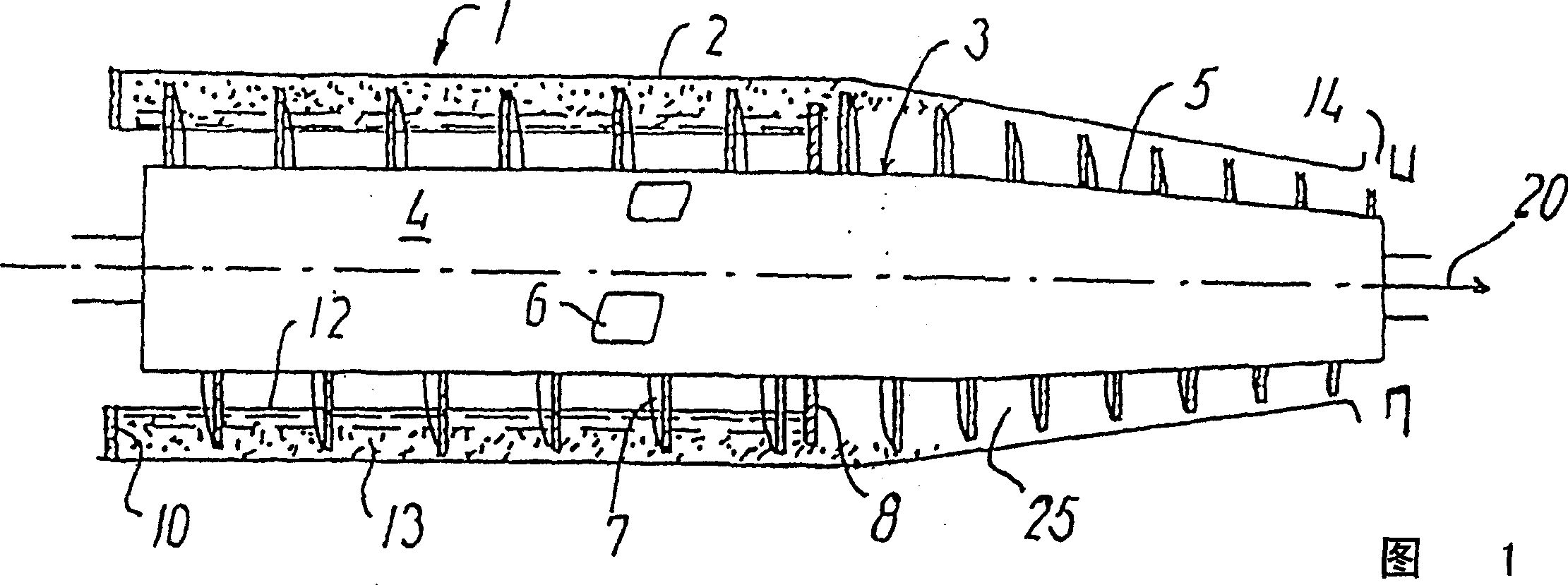
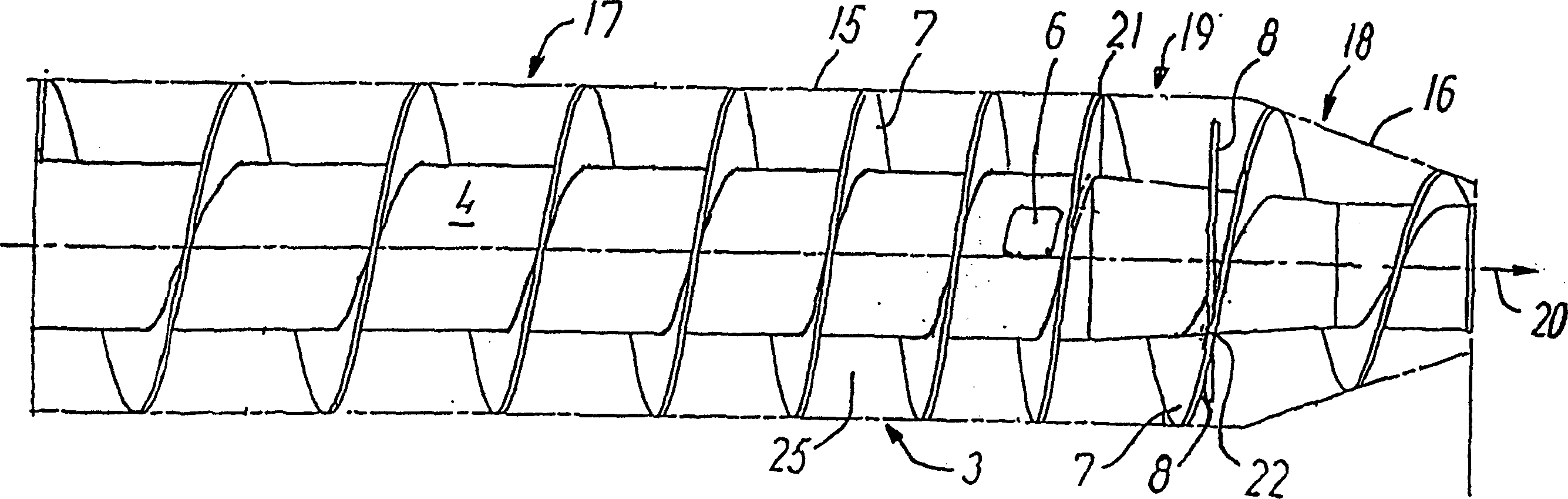
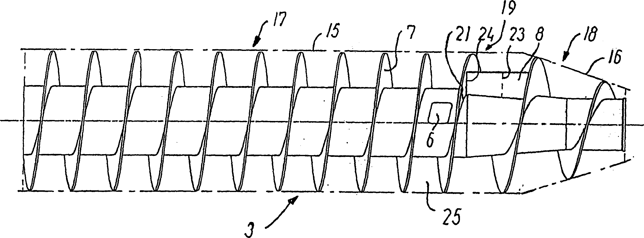
[0024] The decanter centrifuge 1 among Fig. 1 has the hollow drum 2 with separation chamber, and screw conveyor 3 is arranged in the separation chamber, and it has the main body 4 with screw rod, and screw rod has helical sheet 7 to wind several turns. The main body 4 is substantially cylindrical and has a conical portion 5 at one end thereof. An inlet opening 6 for the material to be separated is provided in the screw conveyor 3 and a discharge opening 14 for the separated heavy phase is provided in the drum 2 . The light phase 12 is positioned closest to the body 4 of the auger, while the heavy phase 13 is positioned inside the drum 2 , as represented in the figures. The light phase is removed via the discharge side 10 on the drum. The heavy phase is conveyed by the turns of the screw to a discharge opening 14 in the conical end of the bowl. The figure shows that the baffle 8 is an annular disc, perpendicular to the longitudinal or axial axis of the screw conveyor.

[002...


PUM


Abstract

The decanter centrifuge comprises a screw conveyor having a body (4), which carries a screw comprising one or more flights (7, 7') and having a nominal transport speed varying along the longitudinal axis. An inlet (6) is provided in the screw conveyor for the material to be separated. The screw conveyor is provided with a baffle (8, 8') dividing the separation chamber in a substantially cylindrical separation part (17) and an at least partially conical discharge part (18). Immediately upstream of the baffle (8, 8') a transition part (19) is provided between the separation part (17) and the discharge part (18), the screw conveyor having a bigger nominal transport speed in the transition part (19) than in the separation part (17) immediately before the transition part (19), the change of the nominal transport speed being established by a change (21) of the screw pitch.

Description

technical field [0001] The invention relates to a decanter centrifuge for separating a feed material into a light phase and a heavy phase, comprising an elongated drum rotating about its longitudinal axis, said drum having a separation chamber in which Provides a screw conveyor coaxial with the drum, said screw conveyor comprising a body equipped with a screw comprising one or several flight flights and having a nominal delivery speed that varies along the longitudinal axis, useful in screw conveyors an inlet for at least one inlet opening for feeding the material to be separated, and at least one discharge opening for the heavy phase in the bowl at one end of the screw conveyor, wherein the screw conveyor is made to rotate relative to the bowl so as to convey the heavy phase to the heavy phase Phase discharge opening, wherein the screw conveyor is equipped with a baffle positioned between the inlet opening and the discharge opening, which divides the separation chamber into a...

Claims


Application Information

Patent Timeline
Patent Type & Authority Applications(China)
IPC IPC(8): B04B1/20
CPCB04B1/20B04B2001/2041
Inventor K·迪尔克斯B·马森
Owner ALFA LAVAL COPENHAGEN
Features
  • R&D
  • Intellectual Property
  • Life Sciences
  • Materials
  • Tech Scout
  • Unparalleled Data Quality
  • Higher Quality Content
  • 60% Fewer Hallucinations
Learn More