Valve operating system for internal combustion engine

An internal combustion engine and valve technology, which is applied to internal combustion piston engines, valve devices, combustion engines, etc., can solve the problems of reducing cylinder pressure and not having a decompression function, and achieve the effect of simple structure and cost reduction.

Inactive Publication Date: 2005-08-03
HONDA MOTOR CO LTD
View PDF0 Cites 6 Cited by
  • Summary
  • Abstract
  • Description
  • Claims
  • Application Information

AI Technical Summary

Problems solved by technology

[0003] However, the conventional valve device does not have a decompression function, although the exhaust gas recirculation function can be brought into play, that is, when the internal combustion engine is started, the exhaust valve is slightly opened in the compression stroke in order to reduce the load of the start-up operation. Appropriately reduce the pressure in the cylinder

Method used


Image

  • Valve operating system for internal combustion engine
  • Valve operating system for internal combustion engine
  • Valve operating system for internal combustion engine

Examples


Embodiment Construction

[0066] Next, embodiments of the present invention will be described based on preferred embodiments of the present invention shown in the accompanying drawings.

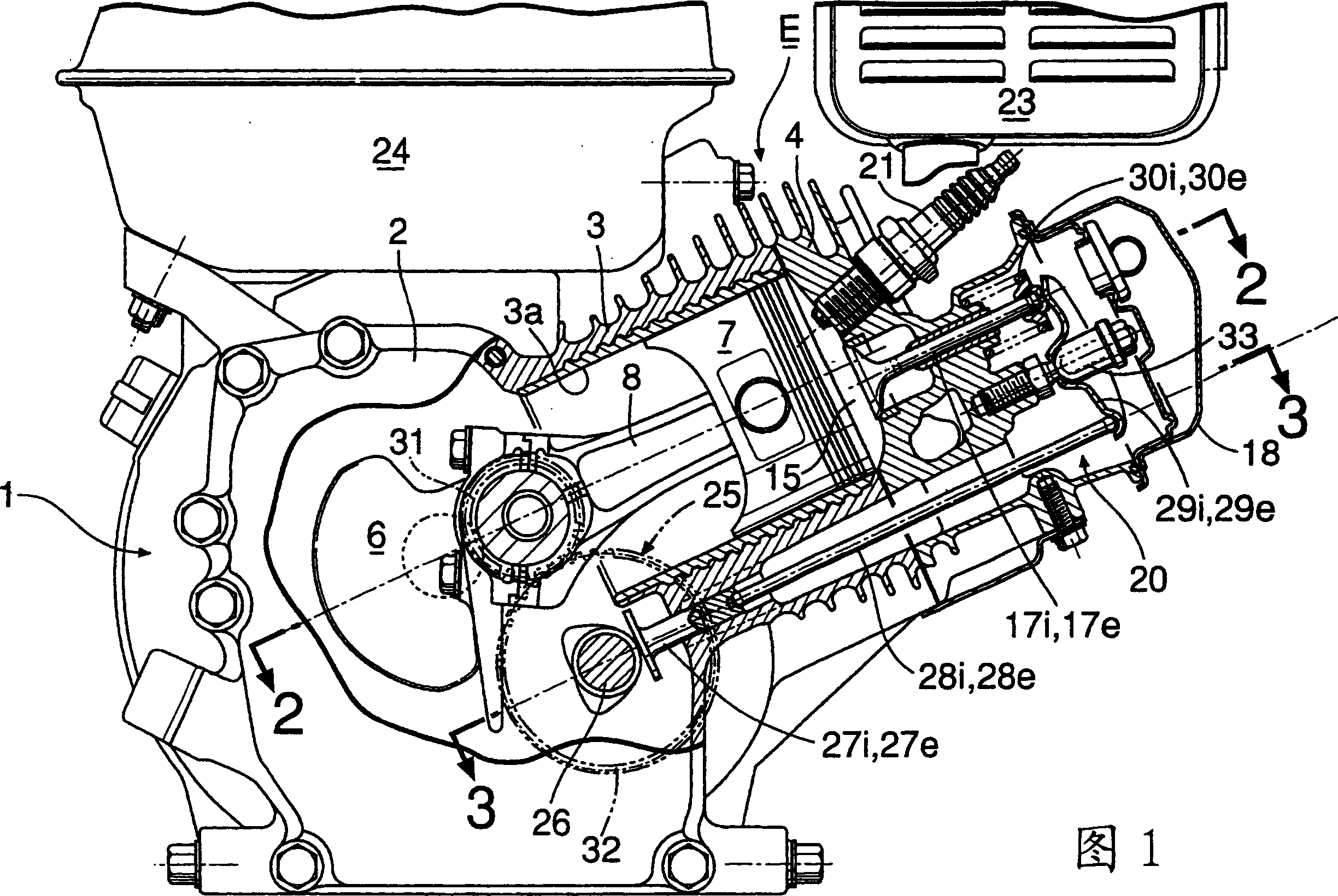
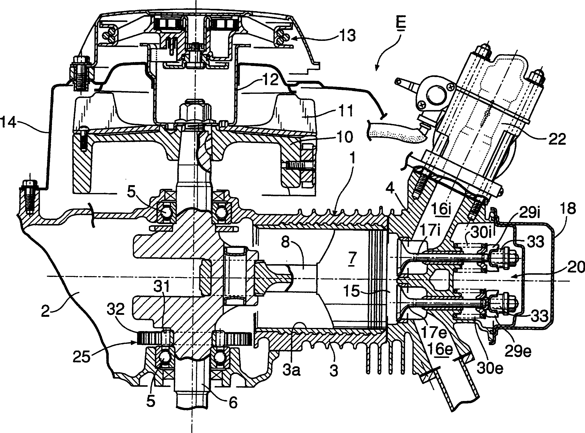
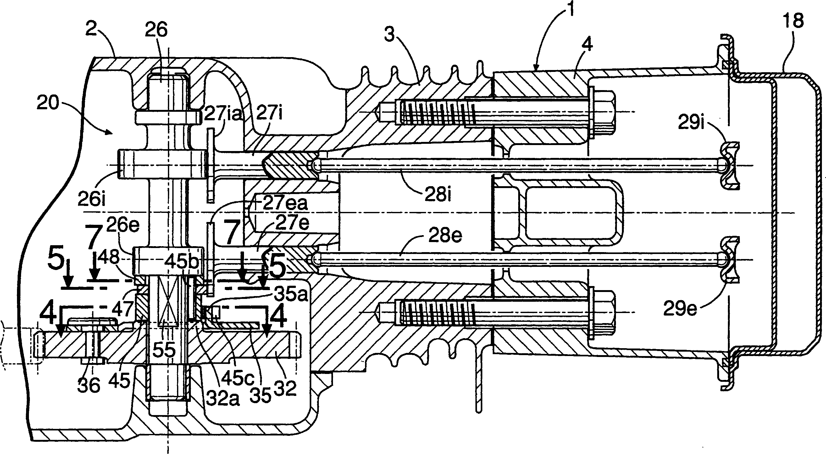
[0067] 1 is a longitudinal sectional side view of an internal combustion engine having a valve apparatus according to a first embodiment of the present invention; figure 2 It is a sectional view along line 2-2 in Fig. 1; image 3 It is a sectional view along line 3-3 in Fig. 1; Figure 4 is along image 3 Sectional view of line 4-4 in Figure 5 is along image 3 Sectional drawing of line 5-5 in Figure 6 With Figure 5 Corresponding work description diagram; Figure 7 is along image 3 Sectional view of line 7-7 in Figure 8 With Figure 7 Corresponding work description diagram; Figure 9 is a schematic diagram showing the working area of ​​the decompression cam part and the exhaust gas recirculation cam part; Figure 10 is a graph showing the relationship between the rotation angle of the crankshaft and th...


PUM


Abstract

A valve operating system includes: a decompression cam member (47); an exhaust gas recirculation cam member (48) that is provided on the camshaft (26), and moves between an inoperative position (F) where the exhaust tappet (27e) is released and an operative position (G) where the exhaust tappet (27e) is operated in a valve opening direction in an intake stroke of the engine (1); and a common centrifugal mechanism that is driven by the camshaft (26) to operate the decompression cam member (47) to the operative position (C) in a starting rotation region of the engine (1) and to the inoperative position (D) after the starting, and operate the exhaust gas recirculation cam member (48) to the inoperative position (F) in a low speed operation region of the engine (1) and to the operative position (G) in a high speed operation region. Thus, the valve operating system can exert both a decompression function and an exhaust gas recirculation function.

Description

technical field [0001] The present invention relates to a valve device of an internal combustion engine. The valve device has a camshaft linked with a crankshaft, and is respectively driven by an intake cam and an exhaust cam formed on the camshaft and opens and closes the intake valve and the exhaust cam respectively. An intake cam follower and an exhaust cam follower for a valve, and in particular, relate to a valve device for an internal combustion engine capable of performing a decompression function at start-up and an exhaust gas recirculation function during high-speed operation by using the above-mentioned exhaust valve. Background technique [0002] In the valve device of the internal combustion engine, when the internal combustion engine is running at high speed, the exhaust valve is slightly opened during the intake stroke to make the exhaust gas return to the combustion chamber, so as to suppress the excessive rise of the exhaust gas temperature and suppress the NO...

Claims


Application Information

Patent Timeline
Patent Type & Authority Applications(China)
IPC IPC(8): F01L13/00F01L1/34F01L13/06F01L13/08F02D13/00F02D13/02F02D13/08
CPCF02M25/0752F01L2820/035F01L1/183Y02T10/18F02D13/0273F02D13/0242F02D2013/0292F01L13/085F01L1/026F01L1/146Y02T10/121F01L2800/10F02M26/01Y02T10/12F16B7/00F16L27/08
Inventor 鹿岛壮二千叶省作山田义和古贺响
Owner HONDA MOTOR CO LTD
Why Eureka
Try Eureka