Robot system

A technology of manipulators and coordinate systems, applied in the field of manipulator systems, can solve problems such as increasing user burden, achieve the effect of reducing teaching costs and ensuring accuracy

Active Publication Date: 2005-12-07
FANUC LTD
View PDF3 Cites 34 Cited by
  • Summary
  • Abstract
  • Description
  • Claims
  • Application Information

AI Technical Summary

Problems solved by technology

[0008] The method of using the existing jig in this way will increase the user's burden no matter what, so it is strongly required to improve

Method used


Image

  • Robot system
  • Robot system
  • Robot system

Examples


Embodiment Construction

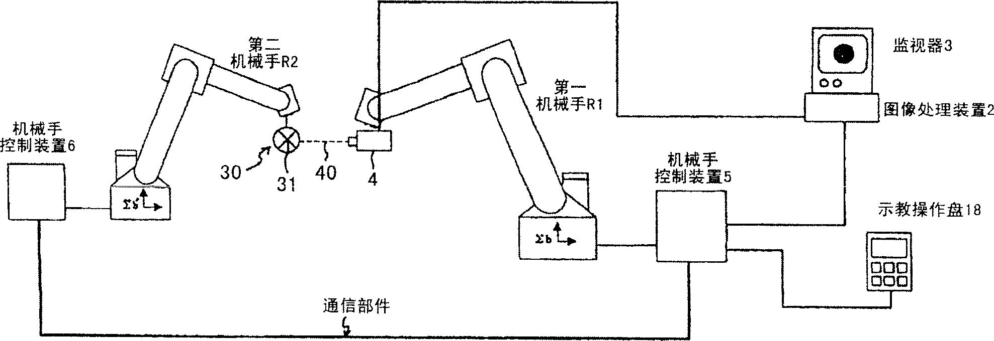
[0039] Hereinafter, embodiments of the present invention will be described sequentially with reference to the drawings. first, figure 1 It is a schematic diagram showing the overall structure in one embodiment of the present invention. In this figure, the manipulators to be calibrated are manipulator R1 and manipulator R2, which are connected to respective manipulator control devices 5 and 6 .

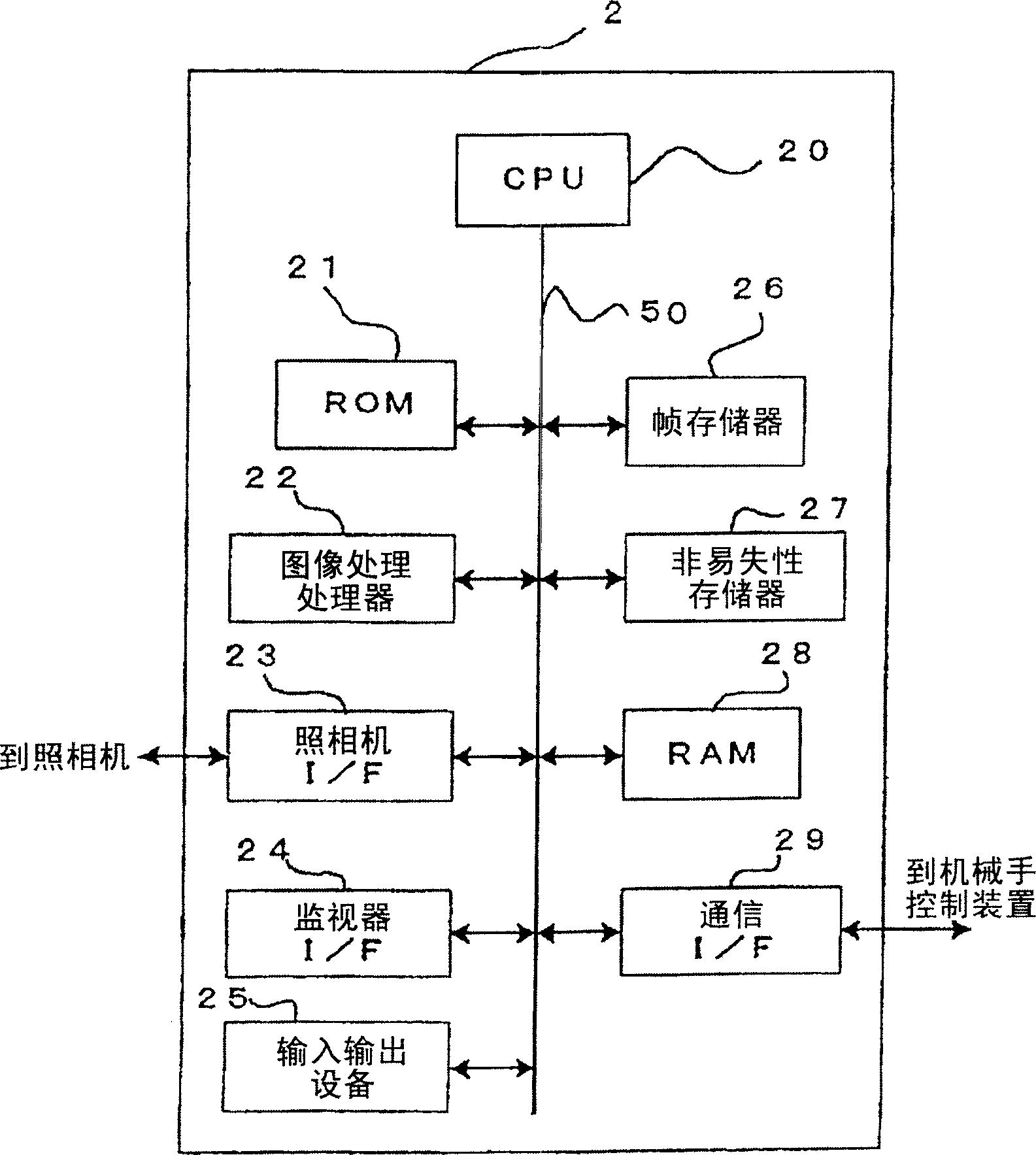
[0040] A camera 4 is attached to the front end of the arm of one robot arm (here, the first robot arm) R1. The camera 4 is, for example, a CCD camera, and is a known light-receiving device having a function of detecting a two-dimensional image through a light-receiving surface for imaging (CCD array surface). In addition, as will be described later, a PSD (Position Sensing Detector: Position Sensing Detector) may be used as the light receiving device. A camera 4 is connected to an image processing device 2 having a monitor 3 constituted by LCD, CRT, or the like.

[0041] The charac...


PUM


Abstract

A robot system comprising a first robot (R1) with a camera of a visual sensor mounted thereon and a second robot (R2) having a feature portion, is disclosed. The robots (R1, R2) are set in the first initial states (G1), from which the first robot (R1) or the second robot (R2) is moved so that the image of the feature portion assumes a target position or size (G2), thereby to store the present positions (P1, Q1) (G3). The same process is repeated N times (N 3) while changing the positions of the initial states of the robots (G4). Based on the positions P1,...., PN and Q1,....., QN obtained by the N repetitive above processes, a matrix T indicating the coordinate conversion from GBP b to GBP b' is determined. One or two robot control units may be provided. As a result, the calibration to determine relative positions between the robots can be carried out easily and with high accuracy, thereby reducing the jig-related cost.

Description

technical field [0001] The present invention relates to a manipulator system including a plurality of manipulators, and more particularly, to a technique for performing calibration related to relative positions between manipulators included in the manipulator system simply and with high accuracy. The robot system according to the present invention is useful, for example, in applications such as conveying a workpiece or processing a workpiece by coordinating a plurality of robots. Background technique [0002] As one type of system using industrial robots, there is a system that performs necessary operations (transportation, processing, etc.) through coordinated operations between two robots. In such a system, the slave robot needs to calculate the position of the moving target from the position of the leader robot. In order to perform this calculation correctly, it is necessary to know the relative positional relationship of the robot coordinate system set on each robot in ...

Claims


Application Information

Patent Timeline
Patent Type & Authority Applications(China)
IPC IPC(8): B25J13/08B25J9/10B25J9/16G05B19/18G05B19/19
CPCB25J9/1682G05B2219/39045B25J9/1692G05B2219/39114G05B2219/39397G05B2219/39046
Inventor 伴一训管野一郎山田慎井上俊彦
Owner FANUC LTD
Why Eureka
Try Eureka