
Rolling control method and device

A control method and technology for rolling materials, which are applied in the direction of rolling mill control devices, metal rolling, vibration control, etc., can solve the problems of increased unevenness, near the end where high precision cannot be maintained, and plate thickness changes, etc., to achieve The effect of improving the accuracy of plate thickness control

Inactive Publication Date: 2006-01-11
HITACHI LTD
View PDF3 Cites 11 Cited by
  • Summary
  • Abstract
  • Description
  • Claims
  • Application Information

AI Technical Summary

Problems solved by technology

[0005] If the work rolls are moved in stages, the partial wear of the work rolls can be suppressed, but there is a problem that the thickness of the rolled material near the end of the material changes greatly during the movement.
[0006] In addition, if the intermediate roll is moved, it can relatively cope with the case where the unevenness of the plate thickness near the edge of the material to be rolled is small, but there is a problem that it cannot be maintained when the unevenness increases for some reason. High-accuracy plate thickness near the end

Method used


Image

  • Rolling control method and device
  • Rolling control method and device
  • Rolling control method and device

Examples


Embodiment Construction

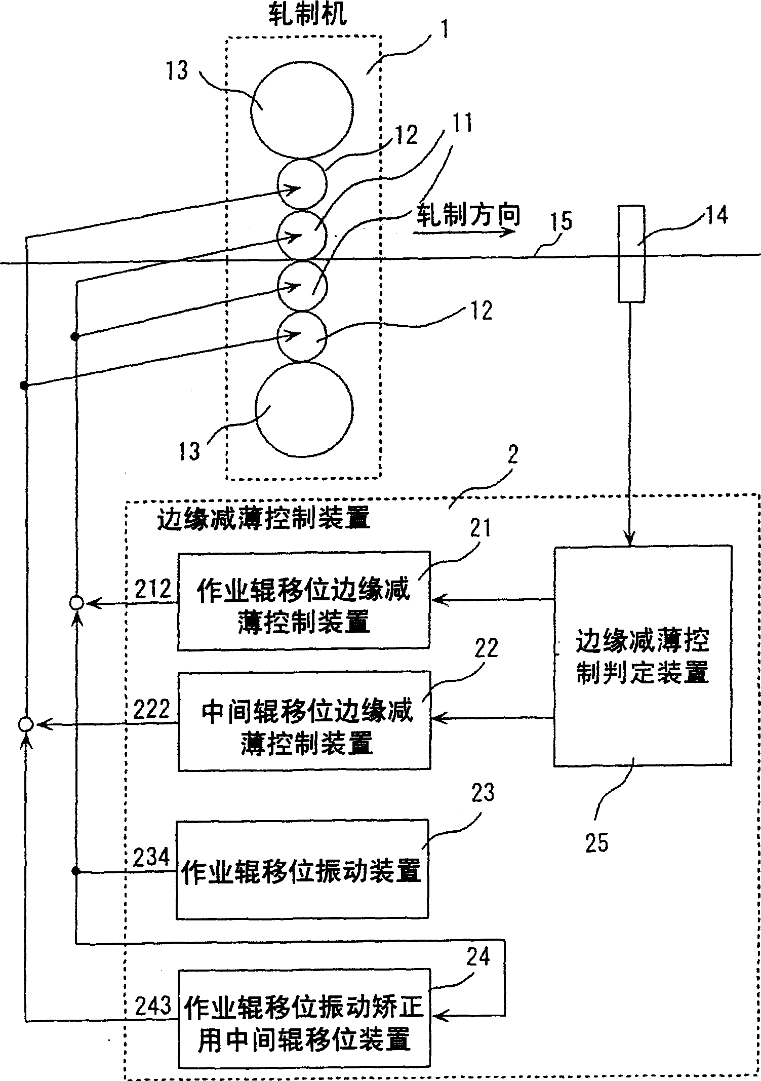
[0018] Hereinafter, the thickness distribution near the end of the material to be rolled is referred to as edge reduction, and the device for controlling the edge reduction is referred to as an edge reduction control device.

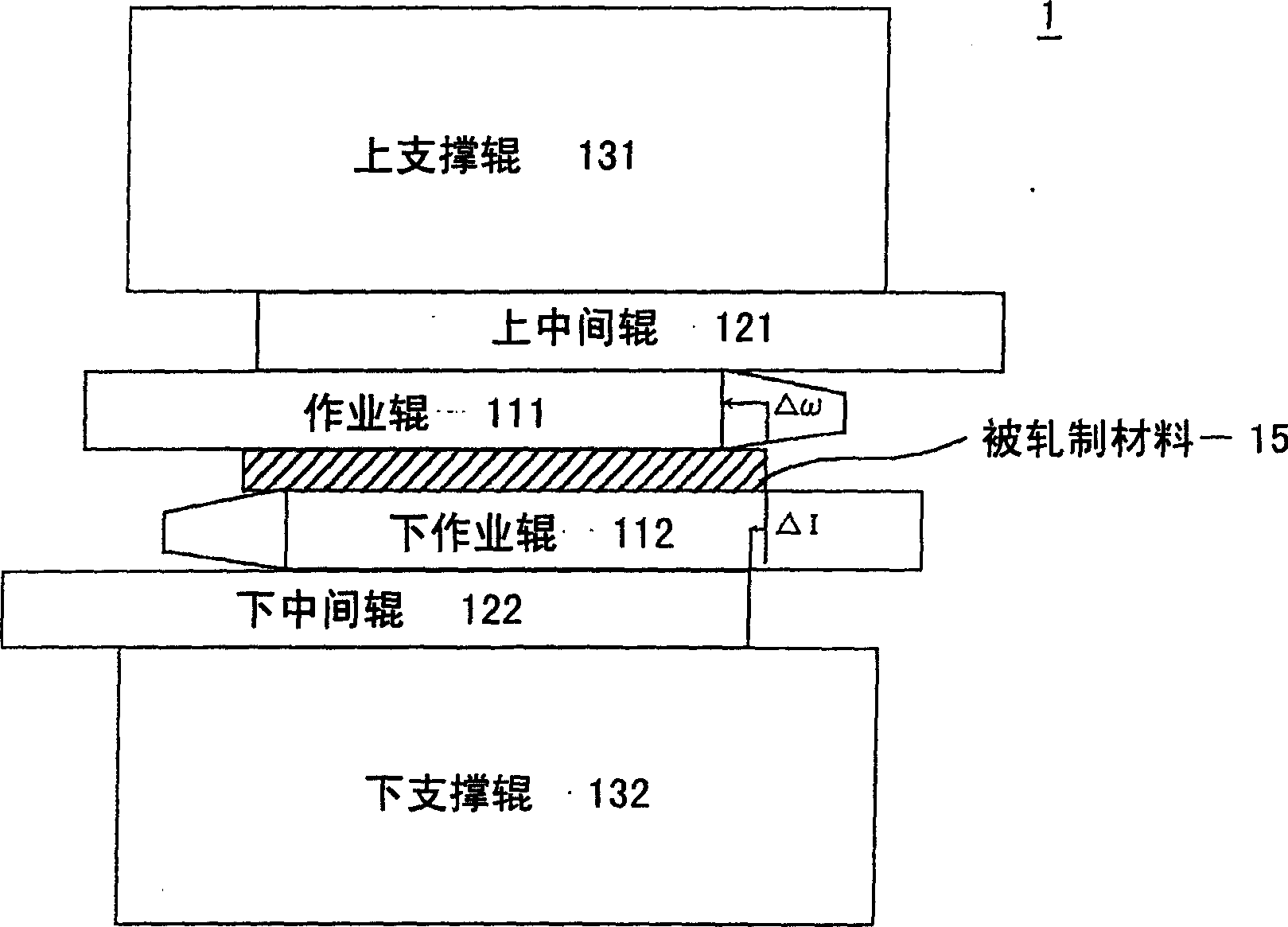
[0019] Fig. 1 is an edge thinning device of the present invention. The rolling mill 1 is composed of work rolls 11 (upper work rolls 111, lower work rolls 112), intermediate rolls 12 (upper intermediate rolls 121, lower intermediate rolls 122) and back-up rolls 13 ( Upper support roller 131, lower support roller 132) constitute. In FIG. 1 , only one rolling mill is described, but a table rolling mill having a plurality of rolling mills having work rolls 11 , intermediate rolls 12 and backup rolls 13 arranged in series also has the same control configuration.

[0020] The edge thinning control device 2 performs control using the edge thinning detection value detected by the edge thinning gauge 14 provided on the exit side of the rolling mill 1 . The edg...


PUM


Abstract

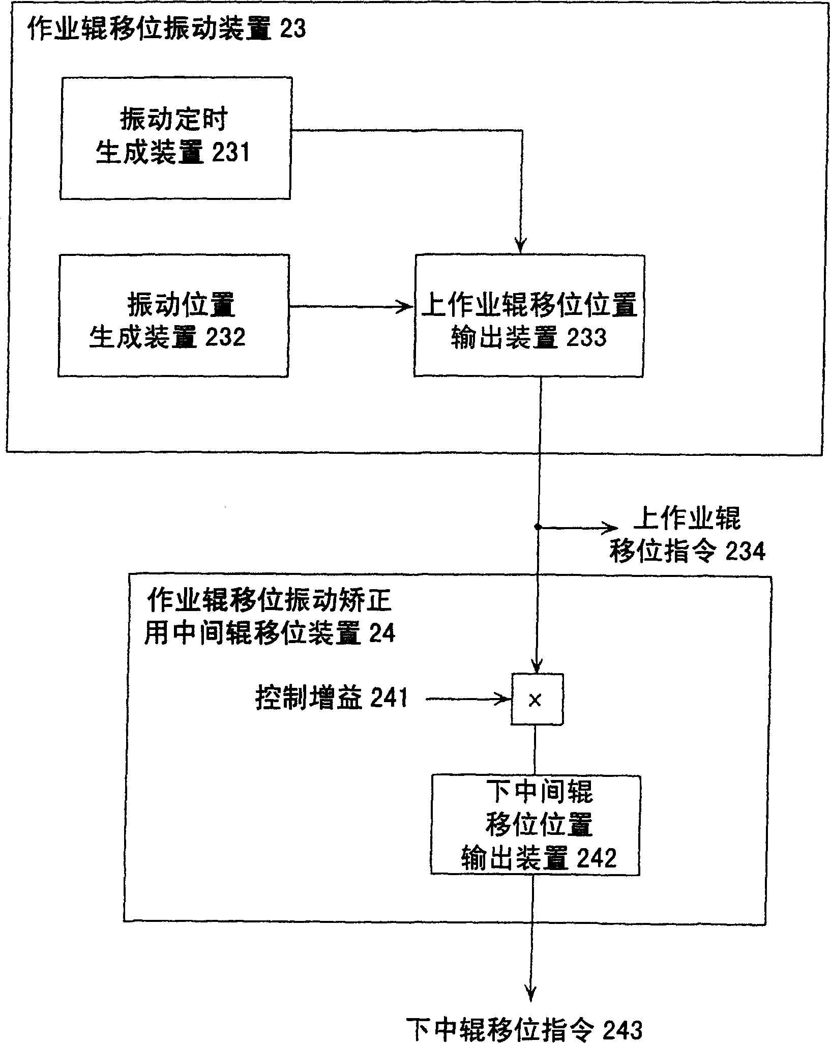
The present invention provides a method and an apparatus for controlling a rolling operation, which method and apparatus can carry out a highly accurate control of the edge drop while suppressing surface defects caused by a roll shift. In a six-high rolling mill, the highly accurate control of the edge drop is carried out by combining a working roll shift and an intermediate roll shift. In addition, a shift oscillation and the control of the edge drop by shifting the intermediate roll are carried out during the rolling operation of the working roll. Further, when the amount of the edge drop cannot be fully controlled by the control of the edge drop by shifting the intermediate roll, the control of the edge drop is carried out by shifting the working roll. By this method, the deviation of the edge drop can be controlled to a minimum while suppressing the generation of the defects on the surface of a strip to be rolled as much as possible.

Description

technical field [0001] The invention relates to a rolling control method and a rolling control device. Background technique [0002] In rolling control, the thickness accuracy of the rolled material in the width direction is strictly required. In particular, thickness accuracy near the end of the material to be rolled is a problem. For this reason, work rolls with inclined front ends are used and a technique of moving the work rolls in the axial direction is used. This technique is disclosed in, for example, JP-A-60-12213. [0003] When the work roll whose tip is inclined is moved, uneven wear of the work roll occurs at the starting point of the inclined portion. In order to suppress such partial wear, a technique of stepwise moving the work roll (oscillating movement) is employed. Such a technique is disclosed in Japanese Unexamined Patent Publication No. 62-151203, for example. [0004] In addition, it is conceivable to improve the thickness accuracy of the width direc...

Claims


Application Information

Patent Timeline
Patent Type & Authority Applications(China)
IPC IPC(8): B21B37/16
CPCB21B37/007B21B37/16B21B37/22B21B37/24B21B37/40
Inventor 服部哲畑中长则筱田敏秀
Owner HITACHI LTD
Learn More