Electric spanner

An electric wrench and wrench body technology, applied in the field of electric wrenches, can solve the problems of inaccurate adjustment, loose jaws, screwed nuts, etc., and achieve the effects of not tight jaws, simple structure, and strong practicability.

Inactive Publication Date: 2006-03-22
徐群强
View PDF0 Cites 2 Cited by
  • Summary
  • Abstract
  • Description
  • Claims
  • Application Information

AI Technical Summary

Problems solved by technology

[0003] The purpose of the present invention is to provide an easy-to-adjust distance between the jaws of the existing traditional wrench, which is often inaccurate due to the difficulty in adjusting the distance between the jaws of the wrench when it is used in some specific situations, thereby easily causing related nuts to be screwed. An electric wrench that is easy to operate and the nut is not screwed
[0005] The present invention is an improvement to the structure of the existing movable wrench. It is composed of a rechargeable battery, a simple control circuit, a charging circuit, an economical and reliable decelerating motor and a transmission system on the relevant parts of the wrench. Using it to screw the nut can effectively solve the problem of the tiger's mouth. In order to prevent the nut from being screwed, when using this wrench, you only need to press the forward button or the reverse button lightly, and the motor that can rotate forward and reverse will drive the adjusting nut to rotate and adjust the distance between the wrench's mouth. It becomes very convenient if the space is large and the space is too small. The present invention has simple structure and strong practicability

Method used


Image

  • Electric spanner
  • Electric spanner
  • Electric spanner

Examples


Embodiment Construction

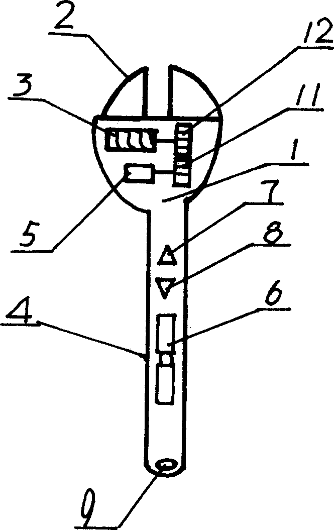
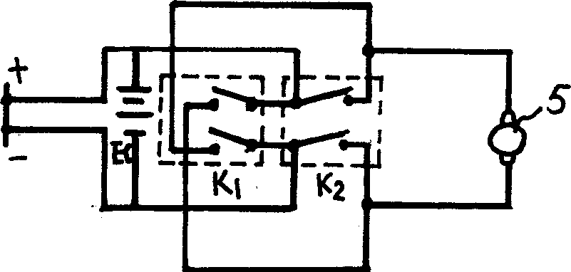
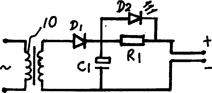
[0010] Further illustrate the present invention in conjunction with accompanying drawing and embodiment, the present invention is made up of wrench body 1, tiger's mouth 2, adjustment nut 3 and handle 4 by the wrench, the wrench body 1 below wrench adjustment nut 3 is provided with deceleration motor 5, handle 4 The rechargeable battery 6, the charging circuit, the control circuit and the charging socket 9 provided at the end of the handle 4 are formed in the cavity; the gear 11 connected to the shaft end of the reduction motor 5 meshes with the gear 12 connected to the adjustment nut; the rechargeable battery 6 is composed of two Section 7 rechargeable battery, charged by the set charging circuit, the charging circuit is composed of transformer 10, diode D1, capacitor C1 and resistor R1, diode D1, capacitor C1 constitute a half-wave rectifier filter circuit, resistor R1 is used for current limiting, diode D2 is a light-emitting diode for indication; the rechargeable battery 6 ...


PUM


Abstract

The electric spanner has reducing motor set below the adjusting nut, the first gear connected to the rotation shaft of the reducing motor, the second gear connected to the adjusting nut and meshed to the first one, and rechargeable battery inside the handle cavity and connected to the charge circuit and connected to motor via DPDT switch. As the improvement of available spanner, the present invention may be used to replace available spanner and has its jaw adjusted via depressing the forward button or backward button slightly. It has simple structure and is practical, especially in oily condition and narrow space.

Description

technical field [0001] The invention relates to an electric wrench, which belongs to the technical field of hardware tools. Background technique [0002] The adjustable wrench currently on the market is one of the necessary tools for repairmen. When in use, the distance between the jaws of the wrench is adjusted by manually adjusting the adjusting nut of the wrench, so as to correspond to nuts of various specifications. In actual use, when repairing some For machines with a lot of oil pollution (such as motorcycles) or the space available for maintenance is too small, it becomes very inconvenient to adjust the nut. Sometimes, due to the misalignment of the gap between the tiger's jaws, some very important nuts are screwed down when they are pulled hard. Scrap, bring very big trouble and economic loss to the user. Contents of the invention [0003] The purpose of the present invention is to provide an easy-to-adjust distance between the jaws of the existing traditional wre...

Claims


Application Information

Patent Timeline
Patent Type & Authority Applications(China)
IPC IPC(8): B25B21/00H02J7/00
Inventor 徐群强
Owner 徐群强
Why Eureka
Try Eureka