Wood rod binding device

A binding device and wood technology, used in construction, construction material processing, scaffolding accessories, etc., can solve the problems of affecting power supply, collapse of spanning, large required quantity, etc., to avoid waste of steel resources, avoid waste of resources, The effect of reducing construction costs

Active Publication Date: 2020-02-11
STATE GRID HEBEI ELECTRIC POWER CO LTD +1
View PDF9 Cites 0 Cited by
  • Summary
  • Abstract
  • Description
  • Claims
  • Application Information

AI Technical Summary

Problems solved by technology

The iron wire is bound and knotted, and when the torsion force exceeds the strength limit of the iron wire after tightening, it will cause the iron wire to break. The most terrible thing is the invisible break, which is not easy to be found. In this case, the spanning frame will cause a flat bar after being stressed Sliding down along the pole, the lashing will loosen, resulting in the collapse of the spanning frame, which will not only cause the object to be spanned to fail to operate normally, affect the power supply, but also may endanger personal safety and cause serious consequences
[0004] On the other hand, the cost of the iron wire used for erecting the spanning frame by the iron wire binding method is too high
During the wiring construction process, due to the large number of objects to be crossed, the amount of iron wire used is also relatively large. According to statistics, the smallest line construction company in Hebei costs as much as 182,560 yuan per year for the iron wire used to erect the spanning frame. It can be seen that the required quantity is large. , Invisibly increased the huge construction cost
Moreover, when the spanning frame is dismantled, the wooden poles and bamboo poles used can be reused, while the iron wires used for binding cannot be reused and can only be treated as waste products, resulting in a lot of waste of resources , which is not conducive to safeguarding the economic interests of power grid enterprises

Method used


Image

  • Wood rod binding device
  • Wood rod binding device
  • Wood rod binding device

Examples


Embodiment 1

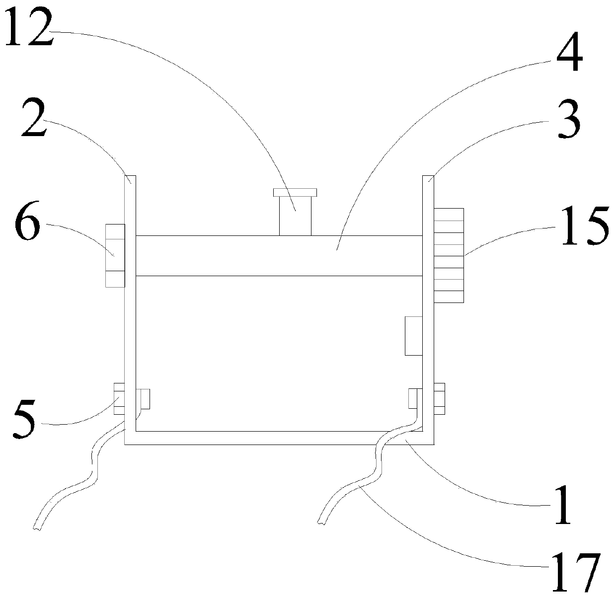
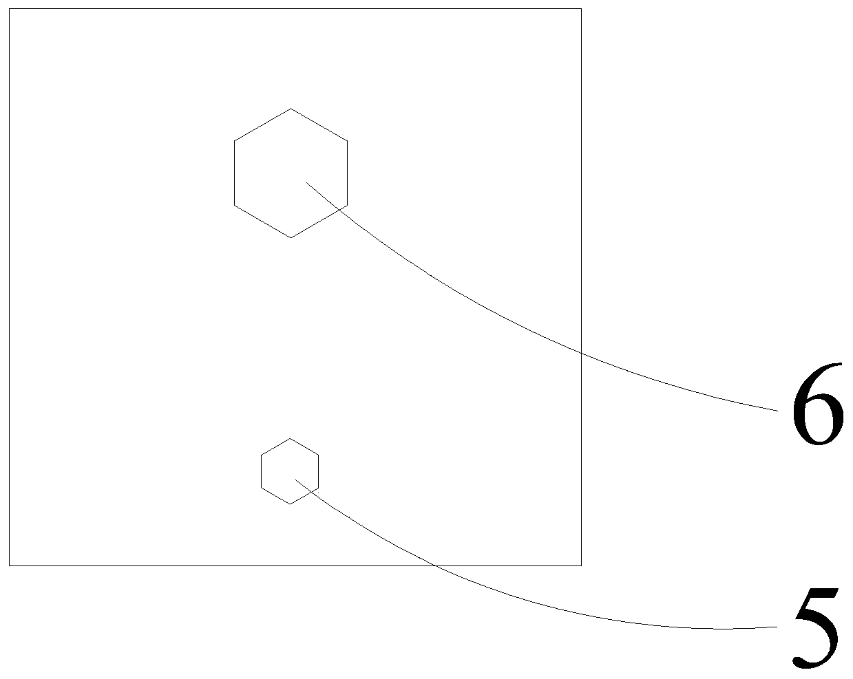
[0044] This embodiment relates to a wooden pole binding device, which is specifically used for wiring of power transmission lines, wherein an exemplary structure is as Figure 2 to Figure 5 shown. It can be seen from the figure that the wooden pole binding device includes a U-shaped metal frame, a steel wire rope and a wire rope fixing piece. The U-shaped metal frame includes a first end face 1 , a second end face 2 and a third end face 3 . Preferably, the U-shaped metal frame is integrally formed. Specifically in this embodiment, it is folded from a flat iron with a length of 20cm and a thickness of 4m. The steel wire rope is wound around the first end surface 1, leaving a free end for binding the wooden pole 18 to be bound. Preferably, the diameter of the steel wire rope 17 is 2.5mm. The wooden rod binding device of this embodiment uses φ2.5 steel wire rope, and its breaking force is 500kg, which ensures the binding force during binding. The potential safety hazards of ...

Embodiment 2

[0062] This embodiment relates to a wooden pole binding device, the structure of which is basically the same as that of the wooden pole binding device in the first embodiment, the difference is that: the ratchet part also includes a driving part, and the driving part includes a driving motor 10 and a driving wheel 11, the teeth of the drive wheel 11 are matched with the oblique teeth 13 of the ratchet 7, one end of the drive motor 10 is fixedly connected to the third end face 3, and the other end is movably connected to the drive wheel 11 (Such as Figure 7 shown). Therefore, the wooden rod binding device of this embodiment is slightly different from the first embodiment when used. After the wire rope is wound and fixed, it is only necessary to make the drive motor 10 work. The specific operation method can be selected from the existing technology. control method in . The drive motor 10 drives the drive wheel 11 to rotate through the connecting shaft, and then the drive whee...


PUM


Abstract

The invention provides a wood rod binding device. The wood rod binding device comprises a U-shaped metal frame, steel wire ropes and steel wire rope fixing pieces. The wood rod binding device takes the U-shaped metal frame as a supporting point, the steel wire ropes are taken as winding tools, the steel wire rope fixing pieces are finally adopted to lock the steel wire ropes, and the binding process is commonly completed by combining the materials into one binding system. According to the wood rod binding device, a traditional iron wire binding mode is completely changed, the wood rod bindingdevice successfully avoids the situations that iron wires are knotted during binding in the prior art, the iron wires are broken due to too large twisting force, and the iron wires are accordingly broken by reaching the fatigue strength limit during binding or are twisted to be broken due to the excessive torsional force, so that the collapse accidents of a crossing frame occur is avoided, the potential safety hazards of the crossing frame collapse are completely eliminated, and personal safety and the safety operation of cross objects are guaranteed. After the wood rod binding device is successfully developed, the wood rod binding device is immediately put into the field for use, and the consistent high evaluation of constructors is obtained in the field use process.

Description

technical field [0001] The invention relates to the technical field of power transmission line equipment, in particular to a binding device for wooden poles. Background technique [0002] During the wiring construction of transmission lines, it often crosses low-voltage lines, 10kV lines, 35kV lines, 110kV lines, 220kV lines and other live lines or communication lines, dirt roads, highways, railways, expressways, orchards, vegetable greenhouses, garden flowers, etc. Lower the span. In order to protect its normal operation during the spanning, we will build spanning frames of different heights and spans according to the different spanning objects. Such as figure 1 As shown, when erecting the spanning frame, each intersection needs to be bound with iron wire. But there are following two problems in iron wire binding. [0003] On the one hand, the iron wire must have a dead knot when binding, which is easy to cause the iron wire to break, and it is not easy to be found. Th...

Claims


Application Information

Patent Timeline
Patent Type & Authority Applications(China)
IPC IPC(8): E04G5/00E04G21/32
CPCE04G5/007E04G21/3209
Inventor 尹志锐王红军胡晓力刘巍王磊刘沛尹浩旭
Owner STATE GRID HEBEI ELECTRIC POWER CO LTD
Why Eureka
Try Eureka