Take-up system

A technology of wire take-up device and winding shaft, which is applied in the field of wire take-up system, can solve the problems of loosening, twisting, poor ring shrinking effect, etc., and achieve the effect of improving stability and safety and reliability

Active Publication Date: 2022-05-27
HANGZHOU VALGEN MEDTECH CO LTD
View PDF9 Cites 0 Cited by
  • Summary
  • Abstract
  • Description
  • Claims
  • Application Information

AI Technical Summary

Problems solved by technology

However, in the process of tightening up the flexible slender member by the wire take-up device, there is a risk that the threaded connection between the wire take-up device and the conveying device will be released in advance, which will lead to poor shrinkage effect
In addition, there is a risk that the threaded connection between the take-up device and the delivery device will become tighter and tighter, which will make it difficult to detach the connection between the take-up device and the delivery device, and the operation risk is high

Method used


Image

  • Take-up system
  • Take-up system
  • Take-up system

Examples


Embodiment Construction

[0042] The technical solutions in the embodiments of the present invention will be clearly and completely described below with reference to the accompanying drawings in the embodiments of the present invention. Obviously, the described embodiments are only a part of the embodiments of the present invention, not all of the embodiments. Based on the embodiments of the present invention, all other embodiments obtained by those of ordinary skill in the art without creative efforts shall fall within the protection scope of the present invention.

[0043] Furthermore, the following descriptions of the various embodiments refer to the accompanying drawings to illustrate specific embodiments in which the invention may be practiced. Directional terms mentioned in the present invention, such as "up", "down", "front", "rear", "left", "right", "inside", "outside", "side", etc., only Reference is made to the directions of the accompanying drawings, therefore, the directional terms used are...


PUM


Abstract

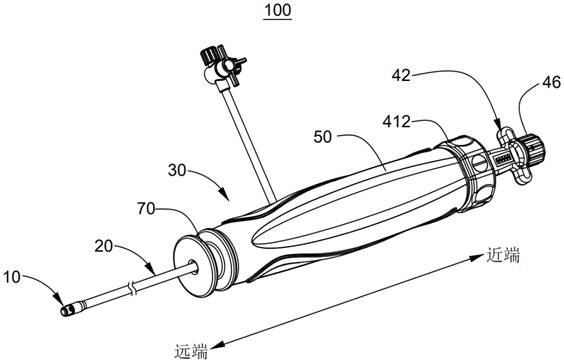
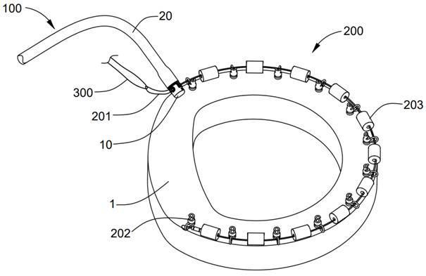
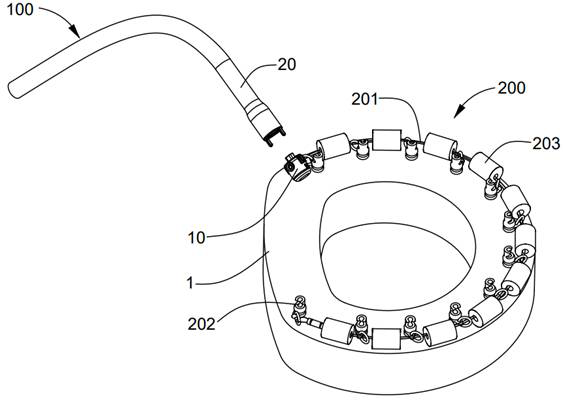
The invention provides a take-up system. The take-up system comprises a take-up device, a conveying device and an operating handle. The take-up device comprises a winding shaft, and the winding shaft is used for winding the flexible long and thin piece. The conveying device comprises a connecting rod and a connecting pipe which are movably sleeved. The operating handle comprises a driving assembly, the driving assembly comprises a first rotating part and a second rotating part which are movably sleeved, the near end of the connecting pipe and the first rotating part are connected for synchronous movement, and the near end of the connecting rod and the second rotating part are connected for synchronous movement; wherein the take-up system has a first state and a second state, in the first state, the first rotating part and the second rotating part relatively stop rotating, in the second state, the first rotating part and the second rotating part can relatively rotate, and the second rotating part moves in the axial direction relative to the first rotating part so that the take-up system can be converted into the second state from the first state. When the take-up system is in the first state, in the process of driving the winding shaft to wind the flexible slender piece, the winding shaft, the connecting pipe and the connecting rod rotate synchronously.

Description

technical field [0001] The invention belongs to the technical field of medical devices, and in particular relates to a wire take-up system. Background technique [0002] Mitral regurgitation (abbreviation: MR) is a heart valve disease that causes blood to flow back from the left ventricle to the left atrium due to insufficiency of the mitral valve. Currently, mitral valve annulus is often reduced in size by mitral annuloplasty to reduce mitral regurgitation. For example, several anchors connected in series by flexible elongated members can be implanted on the mitral valve annulus, and then the redundant flexible elongated members can be tightened by a wire take-up device to shorten the distance between adjacent anchors. The wire device remains in the human body along with the anchor and the flexible elongated member, so as to realize the shrinking of the mitral valve annulus to treat mitral valve regurgitation. [0003] In the prior art, the wire take-up device is connecte...

Claims


Application Information

Patent Timeline
Patent Type & Authority Applications(China)
IPC IPC(8): A61F2/24
CPCA61F2/246A61F2/2442A61F2/2445
Inventor 张庭超匡经旭郭荣辉
Owner HANGZHOU VALGEN MEDTECH CO LTD
Why Eureka
Try Eureka