Hand-held setting tool with connection means for a positioning device

a positioning device and connection means technology, applied in the direction of stapling tools, manufacturing tools, nailing tools, etc., can solve the problems of limiting the angle at which a setting process is still possible, affecting the safety of the actuation of the setting tool, and reducing the surface pressure in the contact region. , to achieve the effect of good access to the recess and reducing the surface pressure in the contact region

Active Publication Date: 2011-03-29
HILTI AG
View PDF20 Cites 6 Cited by
  • Summary
  • Abstract
  • Description
  • Claims
  • Application Information

AI Technical Summary

Benefits of technology

[0012]Another object of the present invention is a setting tool of the type discussed above in which the safety device provides for actuation of a setting process with remote actuation means in a predetermined angular region of orientation of the setting tool with respect to the vector of the gravitational force, and enables an adequate switching stroke for actuation of the setting tool at a small expenditure of force.
[0017]Advantageously, the blocking members are formed as pin-shaped members. Thereby, a premature release of the blocking position can be prevented when the device is dynamically displaced against a wall or a floor, and the blocking members have a tendency, because of the occurring acceleration forces, to move out of their blocking position. This is because the pin-shaped blocking members contrary to the ball-shaped blocking members block the release over their entire axial length, thus, preventing the premature release of the blocking position.
[0019]It is advantageous, when the at least three channels are inclined to the plane which extends perpendicular to the longitudinal axis, each at an angle between 20° and 50°. This permits, on one hand, a reliable free switching at an orientation transverse to a direction opposite the direction of the vector of the gravitational force or at an orientation slightly inclined to this transverse orientation and, on the other hand, reliably blocks the actuation at an orientation perpendicular to the vector of the gravitational force (horizontal) orientation, or at a dynamic pressure in the direction of the gravitational force.
[0021]It is further advantageous when the recess in the switching element is formed as an annular groove closed in both axial directions of the switching element. This insures a good access of the recess for the blocking members and their easy displacement from the channels into the recess for effecting blocking when the setting tool is displaced in a position in which an actuation is not desired.
[0022]It is further advantageous when the recess in the switching element has walls that limit the recess in an axial direction and that are inclined to the longitudinal axis so that an axial width of the recess diminishes from a radially outer side to a radially inner side. Thereby, the pin-shaped blocking members have, in the blocking position, not a point but linear contact with the inclined walls of the recess. Thereby, the surface pressure in the contact region can be reduced.

Problems solved by technology

The drawback here consists in that the actuation of the setting tool can only be safely prevented when the positioning and actuation device with the setting tool is oriented exactly with the muzzle part facing in the direction of the force of gravity.
However, the drawback of the setting tool of U.S. Pat. No. 7,014,085 consists in that the diameter of the ball defines the maximum movement path of the holder relative to the housing which is available in the release position of the ball and within which all of the necessary functions such as, e.g., initiating of ignition, must be carried out.
Therefore, a very high pressing force is needed for this short movement path.
Another disadvantage consists in that widely different angles result when the setting tool is lifted upward until released, and when the setting tool is lowered until blocked again; that is, the limiting angle at which a setting process is still possible when the setting tool deviates from a vertical orientation opposite to gravitational force can vary dependent on the changes in orientation of the setting tool prior to actuation.
Moreover, when the setting tool is pressed horizontally against a wall or downwardly against a floor by moving the tool up or down, the blocking ball rolls out of its blocking position, and the setting tool becomes inadvertently released.

Method used


Image

  • Hand-held setting tool with connection means for a positioning device
  • Hand-held setting tool with connection means for a positioning device
  • Hand-held setting tool with connection means for a positioning device

Examples


Embodiment Construction

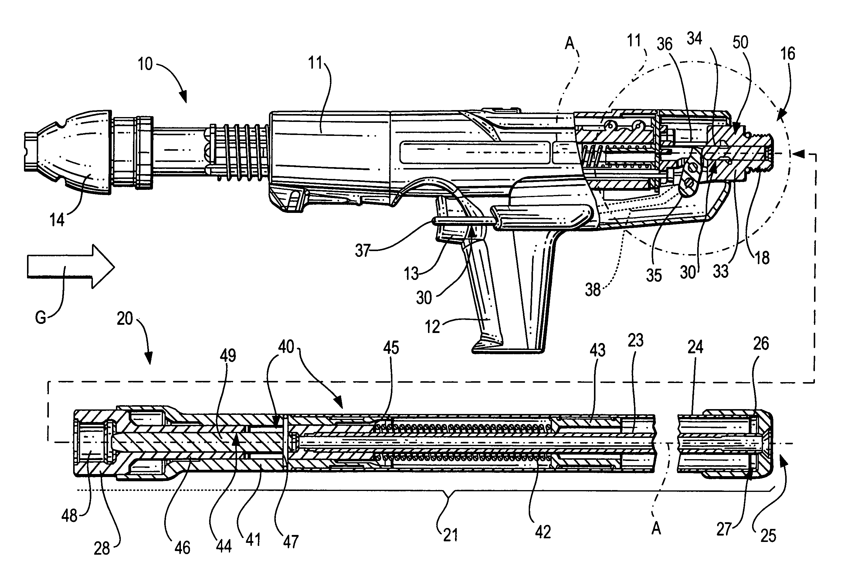
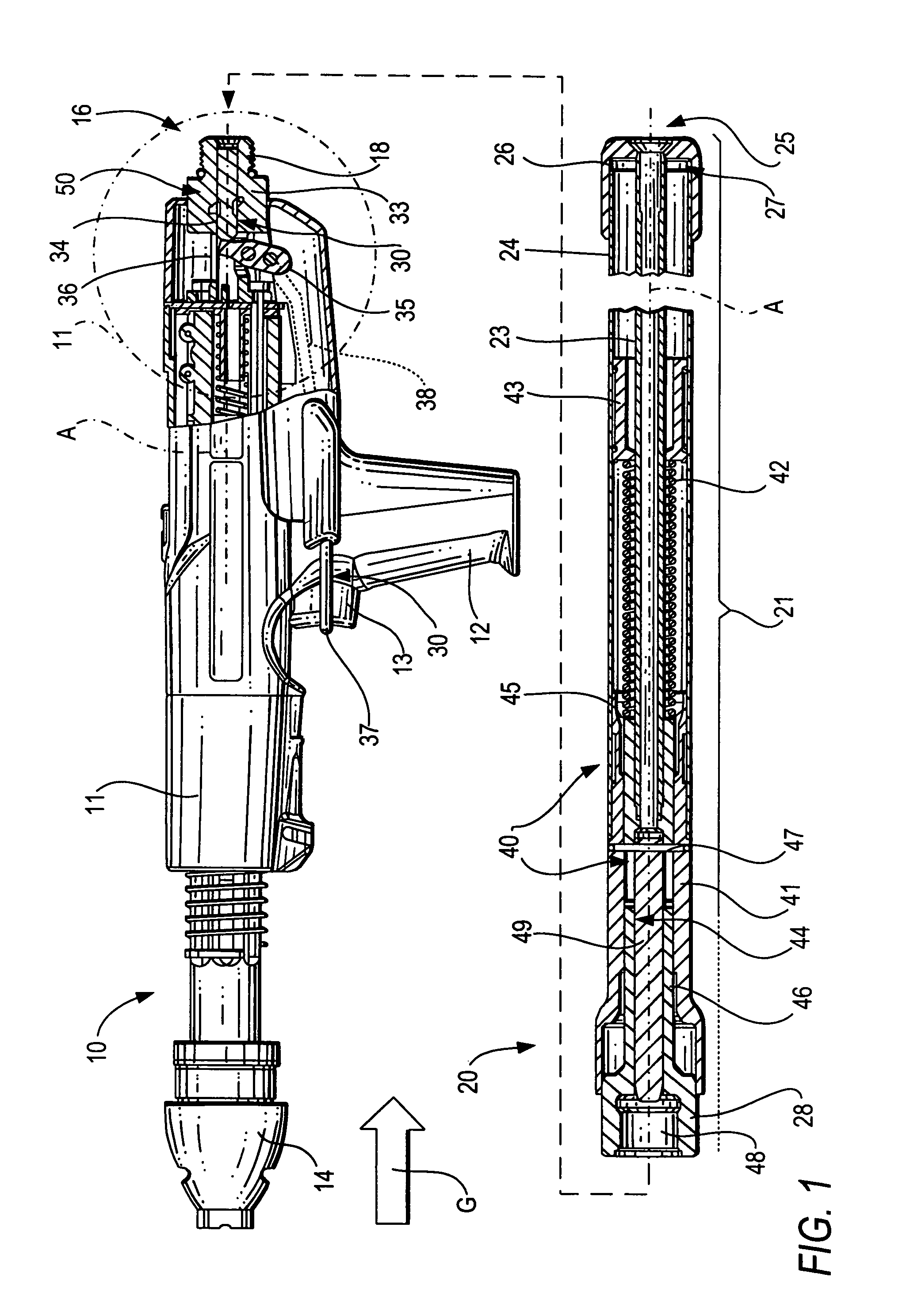
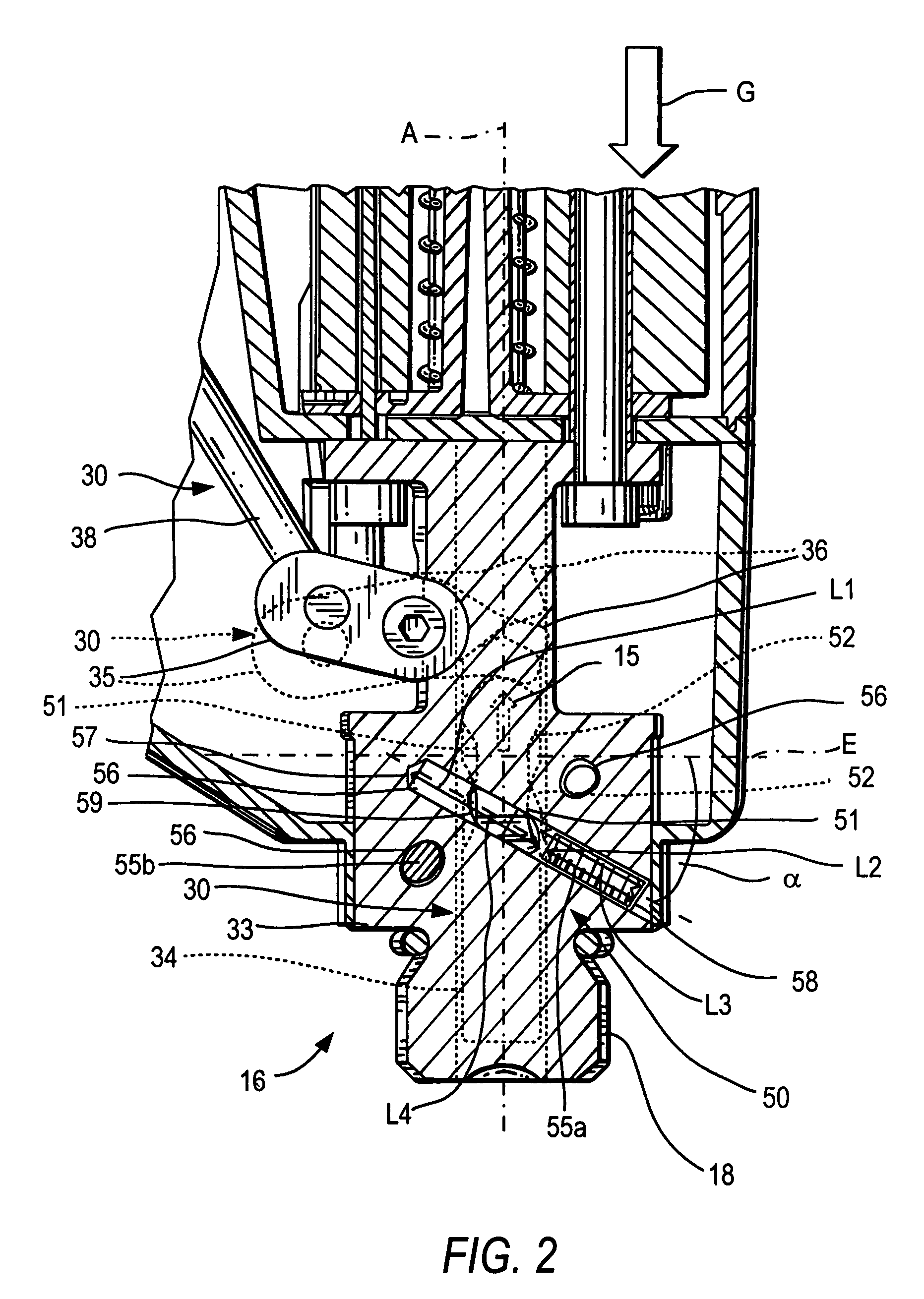
[0030]FIGS. 1 through 5 show a hand-held setting tool 10 according to the present invention and a positioning device 20 with actuating switching means for the setting tool 10 and which can be formed as a modular unit. Such positioning devices 20 are used for elongation of setting tools in order, e.g., to be able to perform an overhead work on ceilings, etc. with the setting tool.

[0031]The positioning device 20, which is shown in FIG. 1, has a rod-shaped holder 21 provided with a coupling element 28 that cooperates with a counter-coupling element 18 forming part of connection means 16 of the setting tool 10, for connecting the rod-shaped holder 21 with the setting tool 10. The coupling element 28 and the counter-coupling element 18 form a releasable connection, so that the positioning device 20 and the setting tool 10 can be assembled together and disassembled. The connection of the coupling element 28 and the counter-coupling element 18 can be formed, e.g., as a threaded or bayonet ...


PUM

PropertyMeasurementUnit
angleaaaaaaaaaa
angleaaaaaaaaaa
angleaaaaaaaaaa

Abstract

A hand-held setting tool (10) includes a connection element (16) for connecting the setting tool (10) with a positioning device (20) having a switching link (30) for connecting the actuation element (24) to the actuation switch (13) of the setting tool (10), and a safety device (50) for preventing actuation of the actuation switch (13) at an orientation of the setting tool (10) other than a predetermined orientation and including at least three blocking members (55a, 55b, 55c) displaceable in at least three separate channels (56) respectively, and receivable in a recess (51) formed in a first, switching element (34) of the switching link (30) with the channels (56) being inclined with respect to a plane (E) extending perpendicular to a longitudinal axis (A) of the positioning device, and with at least three channels (56) intersecting, in some regions, an axial projection of the switching element (34).

Description

BACKGROUND OF THE INVENTION[0001]1. Field of the Invention[0002]The present invention relates to a hand-held setting tool including an actuation switch, connection means for connecting the setting tool to a positioning device and having a counter-coupling element for the positioning device, a structural component, and a mechanical switching link including at least one first switching element displaceable in the structural component along an axis of the setting tool for connecting an actuation element provided on the positioning device with the actuation switch, and a safety device for preventing actuation of the actuation switch of the setting tool at an orientation of the setting tool other than a predetermined orientation.[0003]2. Description of the Prior Art[0004]Positioning tools of the type described above are used, e.g., at overhead works in case of high ceilings when working is possible only using working platforms or ladders. Setting tools, which can be used with such device...

Claims


Application Information

Patent Timeline
Patent Type & Authority Patents(United States)
IPC IPC(8): B25C1/08
CPCB25C1/008
Inventor BLESSING, MATTHIASSCHAEPPER, WALTERSPRENGER, MARKUS
Owner HILTI AG
Why Eureka
Try Eureka