Connector assembly contact having an outwardly projecting primary lance

a technology of connector assembly and contact, which is applied in the direction of connection, electrical apparatus, coupling device connection, etc., can solve the problems of difficult to resolve conflicting demands, and achieve the effects of reducing friction, reducing friction, and reducing friction

Active Publication Date: 2017-05-30
ROBERT BOSCH GMBH
View PDF13 Cites 0 Cited by
  • Summary
  • Abstract
  • Description
  • Claims
  • Application Information

AI Technical Summary

Benefits of technology

[0009]In accordance with specific embodiments of the present invention, a contact is provided for a connector assembly where, on the one hand, superior elasticity properties make possible an inward resilient deformation of an outwardly projecting primary lance with little expenditure of force during an insertion process and a subsequent springing back to the initial position thereof in order to latch the contact into the contact chamber. On the other hand, the primary lance is adapted to have substantial flexural rigidity, at least in relevant regions, to be able to thereby withstand a pull-out force acting on the contact.
[0015]In other words, the primary lance may have a flat cross section in the resiliently deformable region, whereas, in the stiff region, it may feature a cross section provided with a kink, a depression, or a bend. Thus, due to the crimp, the primary lance features a substantially increased flexural rigidity in the stiff region, thereby reducing a risk of the primary lance bending counter to the plug-in direction in the event of a mechanical pulling force on the contact.
[0016]In the stiff region, the crimp may extend from one end adjoining the resiliently deformable region to a maximally outwardly projecting end. Thus, the flexural rigidity of the primary lance may be increased over the entire stiff region by the crimp.
[0022]A further advantage of the contact that is provided may be seen in that the effective length of the primary lance may be configured to be longer than the freely cut lances. This may be utilized, for example, for inwardly crimping an unsupported end of the primary lance, i.e., in a direction toward the housing of the contact. For example, such a crimping makes it possible to effect that the primary lance, which is latched into a contact chamber of the plug connector, does not engage merely by a sharp-edged end face at the projecting end thereof at a recess of the contact chamber, rather, instead, that a force acting on the primary lance may be transferred by the crimped region two-dimensionally to the recess in the contact chamber.

Problems solved by technology

Particularly in the case of miniaturized contacts, where it is necessary to meet stringent mechanical demands in spite of a small size and small material thicknesses, it can be difficult to resolve these conflicting demands, since flexurally stiff primary lances tend to plastically deform in response to a deformation that occurs during an insertion process, for example.

Method used


Image

  • Connector assembly contact having an outwardly projecting primary lance
  • Connector assembly contact having an outwardly projecting primary lance
  • Connector assembly contact having an outwardly projecting primary lance

Examples


Embodiment Construction

[0029]The figures are merely shown schematically and not true-to-scale. Like or similar features are denoted by the same reference numerals in the figures.

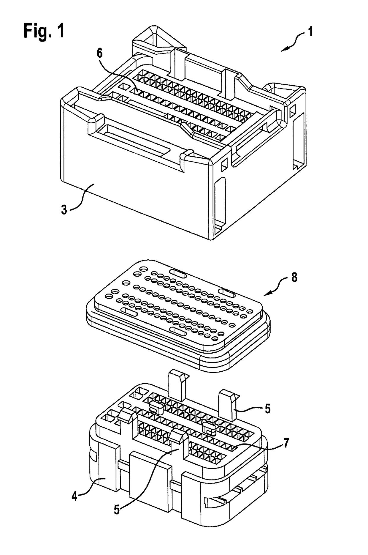
[0030]FIG. 1 shows a plug connector 1 that may be part of a connector assembly for a mating connector. Plug connector 2 may be used, for example, for mechanically and electrically interconnecting a plurality of cables or a cable harness to a control unit in a motor vehicle.

[0031]Plug connector 1 has a housing upper part 3 and a housing lower part 4 that may be mechanically interconnected via locking tabs 5. Configured between housing upper part 3 and housing lower part 4 is a mat seal 8. Provided both in housing upper part 3 and in housing lower part 4 are contact chambers 6, 7 through which cables and contacts fastened thereto (not shown in FIG. 1) may be introduced into plug connector 1 and fastened to snap into place therein.

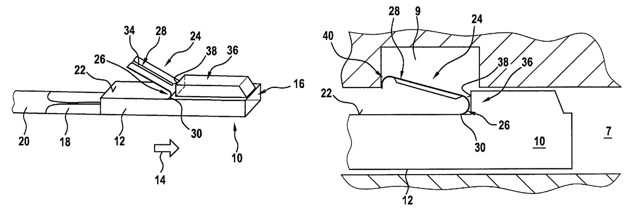
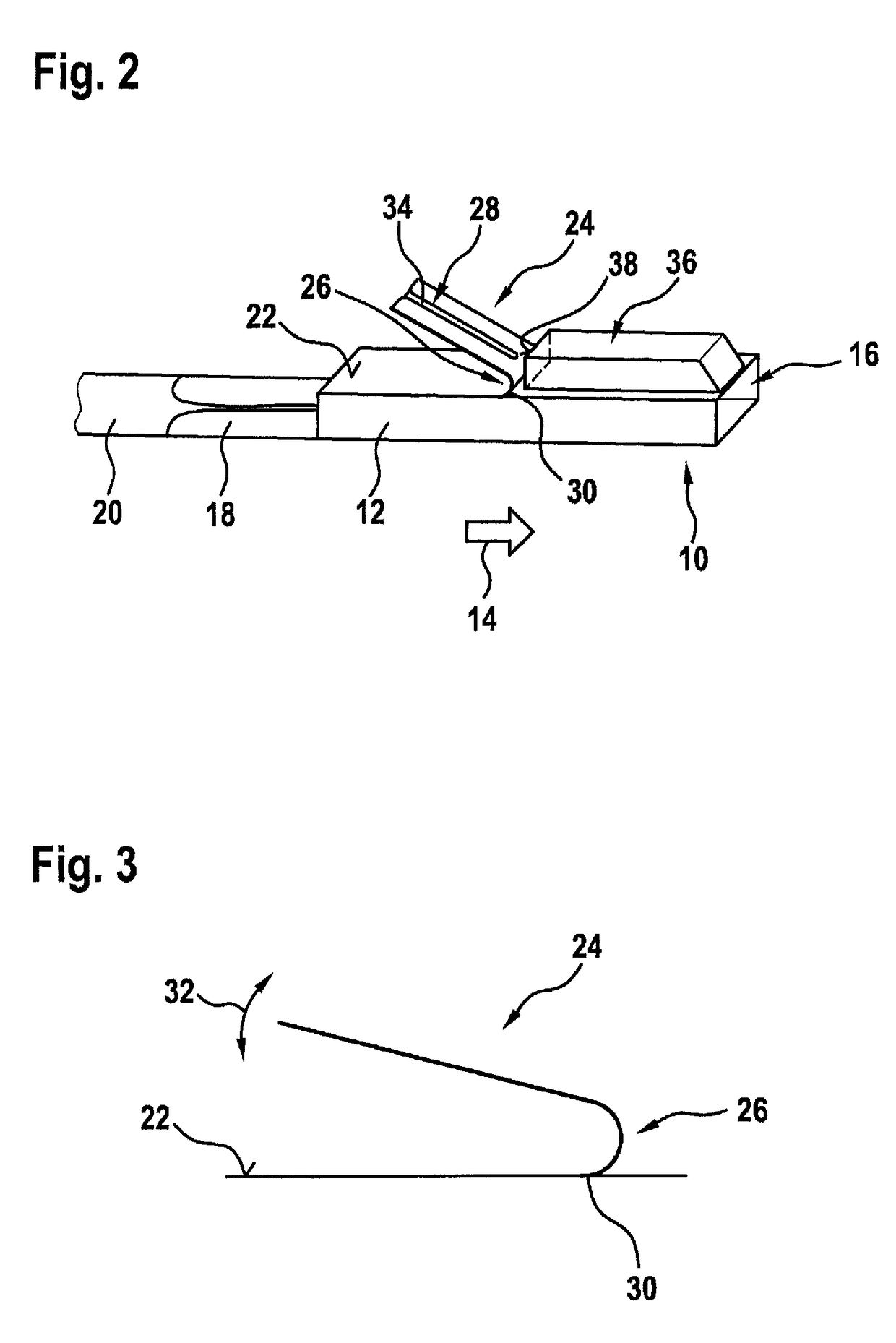
[0032]FIG. 2 illustrates one specific embodiment of a contact 10, depicting how it may be placed in one ...


PUM


Abstract

A contact for a plug connector has: a housing; and a primary lance which projects obliquely outwardly over the housing counter to a plug-in direction and which is inwardly deflectable for restraining the contact plugged into a contact chamber of a plug connector. The primary lance has both a stiffened region and a resiliently deformable region which is curved and extends at least partially in the plug-in direction. The stiffened region has a crimp that extends in the longitudinal direction. A supporting region is additionally provided, against whose contact surface the primary lance rests in response to a tensile load on the contact.

Description

BACKGROUND OF THE INVENTION[0001]1. Field of the Invention[0002]The present invention relates to a contact for a connector assembly and, in particular, to a plug connector equipped with such a contact.[0003]2. Description of the Related Art[0004]In vehicle manufacturing, for example, it is often necessary to interconnect electrical lines. For example, there is a need to interconnect cables or to connect cables to electrical devices. To this end, plug connectors are often used where one or a plurality of contact chambers are provided in a connector housing. A contact connected to an electrical line is placed in each of the contact chambers and latched therein. The contact is designed to produce an electrically conductive connection with a correspondingly designed mating contact of a mating connector, respectively of a socket, upon intermating of the plug connector with the mating connector, respectively the socket.[0005]In the manufacture of such plug connectors, the contacts, onto w...

Claims


Application Information

Patent Timeline
Patent Type & Authority Patents(United States)
IPC IPC(8): H01R13/428H01R13/432
CPCH01R13/432H01R13/428
Inventor HU, ZHENYUSCHMATZ, ULRICH
Owner ROBERT BOSCH GMBH
Why Eureka
Try Eureka