Golf club shaft

Active Publication Date: 2012-12-06
SUMITOMO RUBBER IND LTD
7 Cites 7 Cited by

AI-Extracted Technical Summary

Problems solved by technology

However, the constitution is apt to reduce the strength of the ...

Benefits of technology

[0021]A lightweight golf club shaft suppressing flexural rigidity...

Abstract

A shaft 6 has a plurality of layers a1 to a10. The layers include a bias layer in which an absolute angle θa of a fiber to a shaft axis line is 10 degrees or greater and 70 degrees or less, and a hoop layer in which the angle θa is equal to or greater than 80 degrees. The layers include a full length layer disposed all over in an axis direction of the shaft, and a partial layer partially disposed in the axis direction of the shaft. The partial layer includes back end reinforcing bias layers a4 and a6, and a backend reinforcing hoop layer a5. In the shaft 6, a torsional rigidity value GIt at a point separated by 300 mm from a butt end is 3.5×10⁶ (kgf·mm2/deg) or greater and 5.0×10⁶ (kgf·me/deg) or less.

Application Domain

Technology Topic

PhysicsTorsional rigidity +2

Image

  • Golf club shaft
  • Golf club shaft
  • Golf club shaft

Examples

  • Experimental program(5)

Example

Example 1
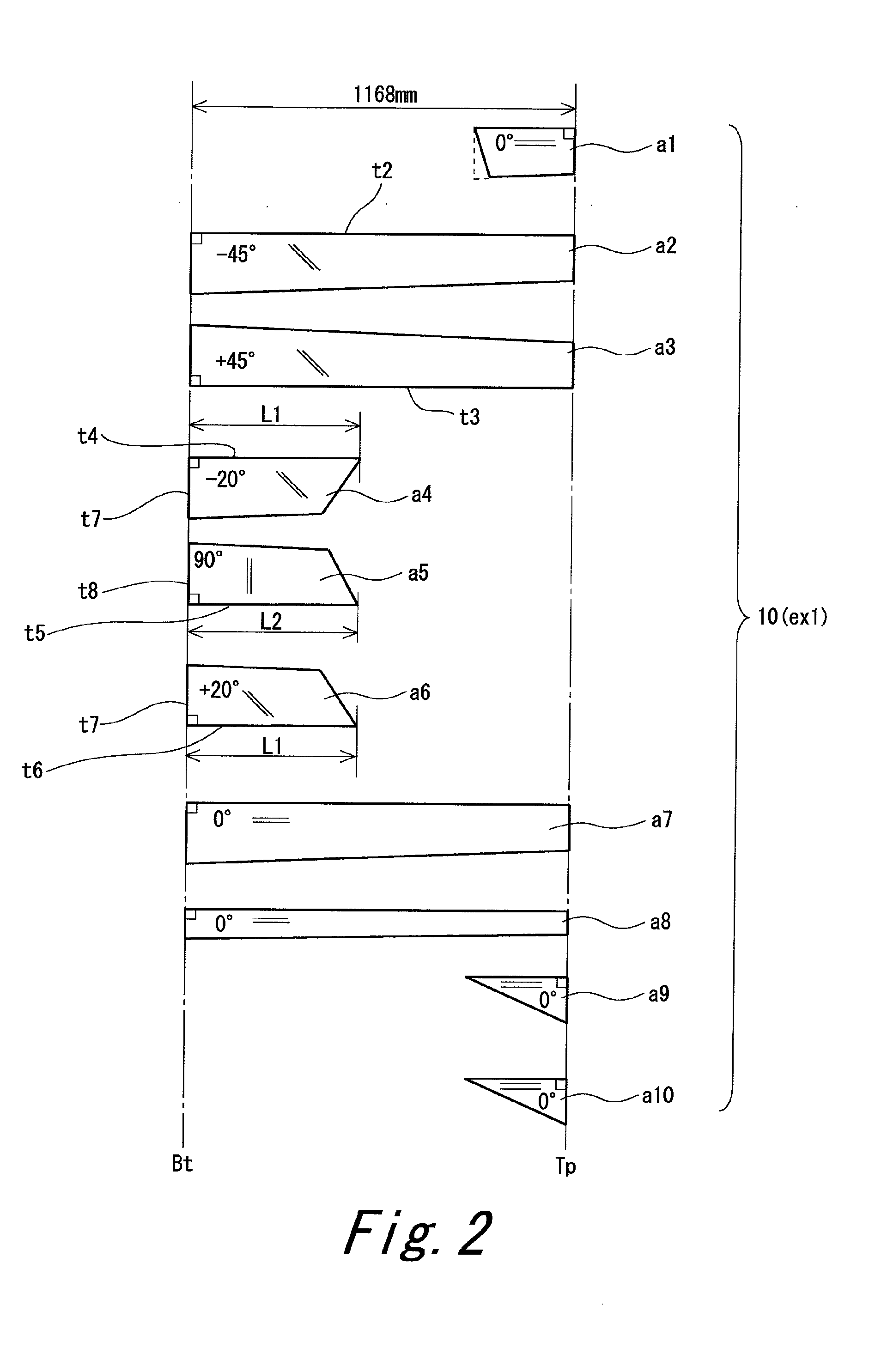
[0119]A shaft having the same laminate constitution as that of the shaft 6 was produced. That is, a shaft having a sheet constitution shown in FIG. 2 was produced. A manufacturing method was the same as that of the shaft 6. A united sheet a456 shown in FIG. 3 was used.
[0120]In example 1, the product name and the number of windings of each sheet were as follows. The specifications of these products are shown in Table 1 described above. [0121] Sheet a1: TR350C-150S (two plies) [0122] Sheet a2: MR350C-100S (two plies) [0123] Sheet a3: MR350C-100S (two plies) [0124] Sheet a4: 2256S-12 (two plies) [0125] Sheet a5: 805S-3 (two plies) [0126] Sheet a6: 2256S-12 (two plies) [0127] Sheet a7: MR350C-100S (two plies) [0128] Sheet a8: MR350C-100S (one ply) [0129] Sheet a9: TR350C-100S [0130] Sheet a10: TR350C-100S
[0131]A commercially available driver head (New XXIO (2011 model) manufactured by SRI Sports Limited.: loft 10.5 degrees) and grip were attached to the obtained shaft, to obtain a golf club according to example 1.

Example

Example 2
[0132]FIG. 4 shows a laminate constitution of a shaft according to example 2. In example 2, the product name and the number of windings of each sheet were as follows. [0133] Sheet a1: TR350C-150S (two plies) [0134] Sheet a2: MR350C-100S (two plies) [0135] Sheet a3: MR350C-100S (two plies) [0136] Sheet a4: 2256S-12 (two plies) [0137] Sheet a5: 805S-3 (two plies) [0138] Sheet a6: 2256S-12 (two plies) [0139] Sheet a7: MR350C-100S (two plies) [0140] Sheet a8: MR350C-100S (one ply) [0141] Sheet a9: TR350C-100S [0142] Sheet a10: TR350C-100S
[0143]A shaft and a golf club according to example 2 were obtained in the same manner as in example 1 except for above.

Example

Example 3
[0144]FIG. 5 shows a laminate constitution of a shaft according to example 3. In example 3, the product name and the number of windings of each sheet were as follows. [0145] Sheet a1: TR350C-150S (two plies) [0146] Sheet a2: MR350C-100S (two plies) [0147] Sheet a3: MR350C-100S (two plies) [0148] Sheet a4: 2256S-12 (two plies) [0149] Sheet a5: 805S-3 (two plies) [0150] Sheet a6: 2256S-12 (two plies) [0151] Sheet a7: MR350C-100S (two plies) [0152] Sheet a8: MR350C-100S (one ply) [0153] Sheet a9: TR350C-100S [0154] Sheet a10: TR350C-100S
[0155]A shaft and a golf club according to example 3 were obtained in the same manner as in example 1 except for above.

PUM

no PUM

Description & Claims & Application Information

We can also present the details of the Description, Claims and Application information to help users get a comprehensive understanding of the technical details of the patent, such as background art, summary of invention, brief description of drawings, description of embodiments, and other original content. On the other hand, users can also determine the specific scope of protection of the technology through the list of claims; as well as understand the changes in the life cycle of the technology with the presentation of the patent timeline. Login to view more.

Similar technology patents

Prepreg, laminate, and molding

PendingUS20220213284A1Excellent strengthReduce molding time and molding costLayered productsVehicle componentsPolymer chemistryTensile shear
Owner:TORAY IND INC

Molybdenum-tungsten alloy and preparation method thereof

InactiveCN106435413AExcellent strengthChromium sesquioxideYttrium
Owner:林海英

Classification and recommendation of technical efficacy words

Why Eureka
Try Eureka