

Boat Bow Shade Cover
- Summary
- Abstract
- Description
- Claims
- Application Information
AI Technical Summary
Benefits of technology
Problems solved by technology
Method used
Image

Examples
Embodiment Construction
[0036]In the following detailed description, reference will be made to the embodiments of the invention, examples of which are illustrated in the accompanying drawings. Whenever possible, like numbers will be used throughout the drawings to refer to the same or like parts. It is to be understood that other embodiments may be utilized and logical, mechanical and, other changes may be made without departing from the scope and spirit of the embodiments. The following detailed description is not to be taken in a limiting sense.
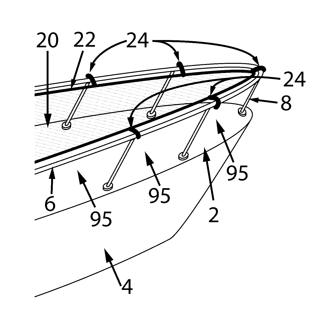
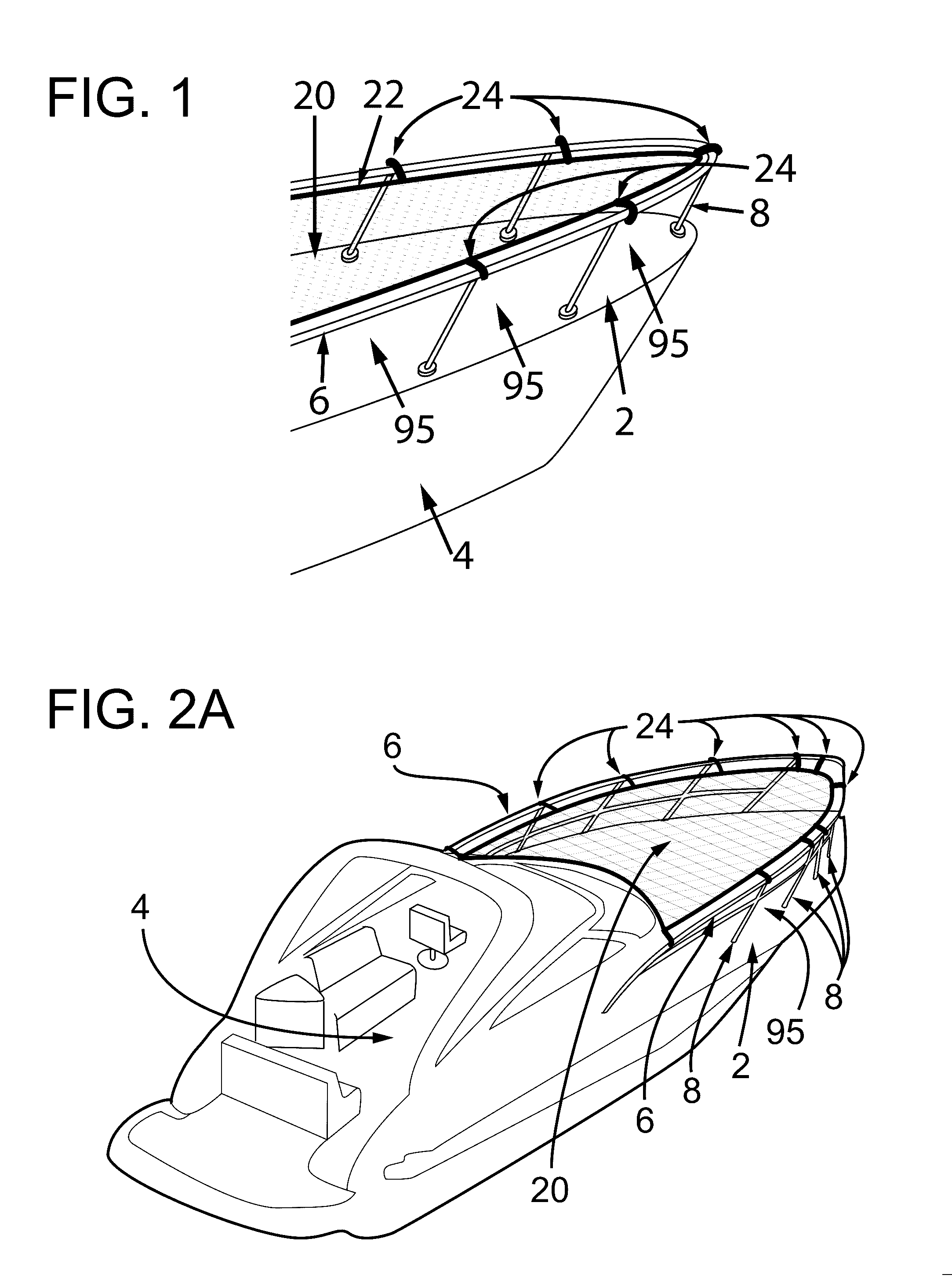
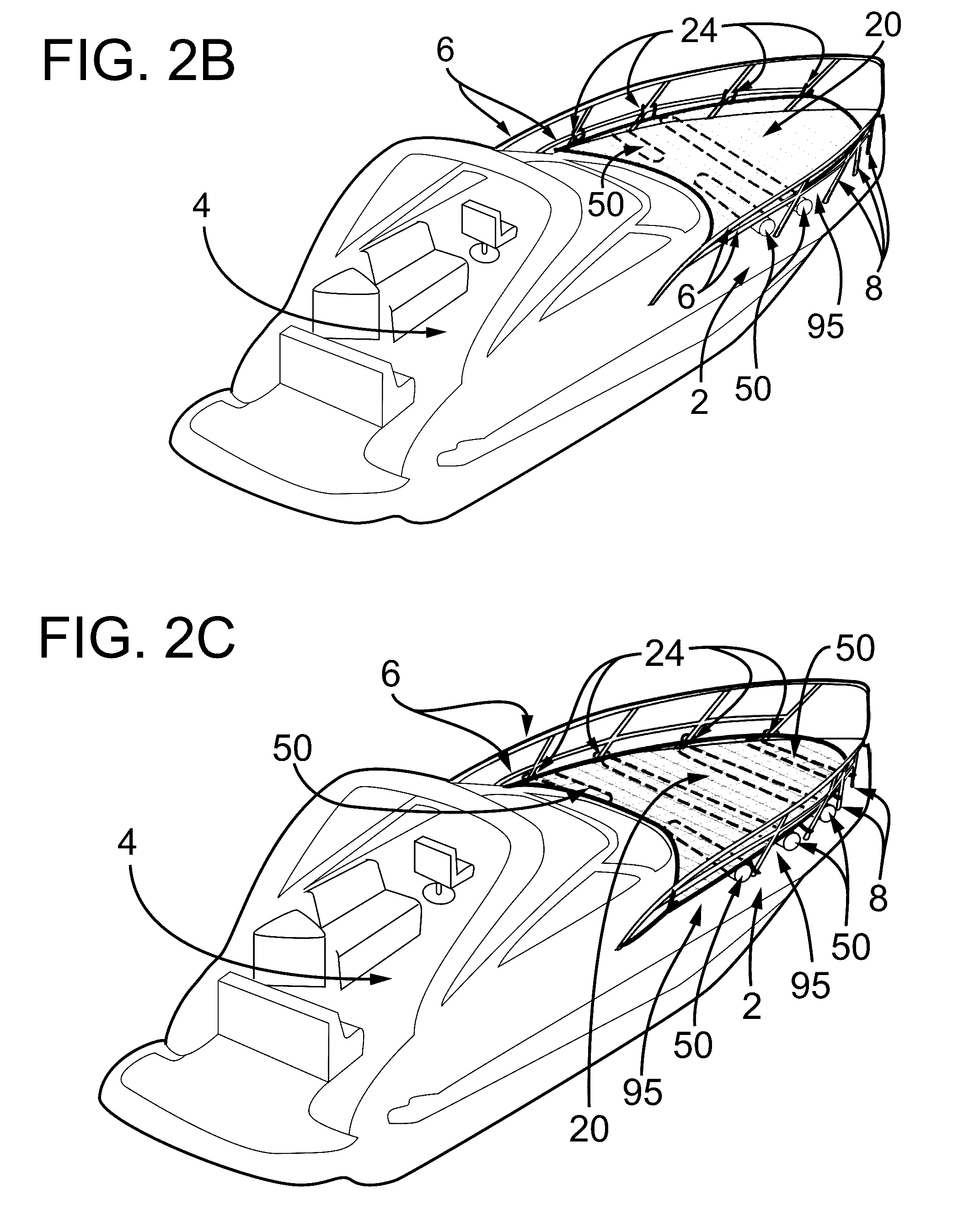
[0037]FIG. 1 shows a basic application of the invention attached to the front or bow 2 of a boat 4. The shade cover 20 conforms to the shape of the railings 6. The means of attachment 24 secure the shade cover 20 from the reinforced edges 22 to the rails 6: The stanchion 8 posts supporting the rail 6 provide clearance preventing said shade cover 20 to make contact with the bow 2 surface. An insulating air space 95 is present throughout the span of the shade cover ...
PUM
 Abstract
Description
Claims
Application Information