Coupling member for connecting a fuel receiving or fuel dispensing part to a fluid line and method for its manufacture

a technology of coupling parts and fluid lines, which is applied in the direction of branching pipes, machines/engines, packaging, etc., can solve the problems of fuel and minimal tearing strength, undesirably high swelling capacity of the third component, and the coupling member can tear off the tank, etc., to achieve reduced swelling capacity, less fuel, and higher strength

Inactive Publication Date: 2005-06-14
NORMA GERMANY GMBH
View PDF14 Cites 11 Cited by
  • Summary
  • Abstract
  • Description
  • Claims
  • Application Information

AI Technical Summary

Benefits of technology

[0005]It is an object of the present invention to improve a coupling member of the aforementioned kind such that less fuel per time unit diffuses through it and a reduced swelling capacity but higher strength is provided than before.
[0007]According to this solution, the second component prevents substantially a diffusion of fuel through the third component and its swelling caused by taking up fuel. The reduced swelling increases the strength of the connection between the third component and the part serving for receiving and dispensing fuel. The degree of swelling is also reduced in that the proportion of the volume of the third component relative to the total volume of the second and third components is reduced. Accordingly, the total strength of the combination of the second and third components is also greater than that of the third component alone.
[0013]Moreover, the first component can have a flange which engages across the third component. In connection with the fact that the first component is tubular and surrounded by the third component, this provides in a simple way a positive-locking and material-bonding connection of the first and third components.
[0015]Moreover, it is an object of the invention to provide a simple method for manufacturing the coupling member according to the invention.

Problems solved by technology

Moreover, the material of the third component has an undesirably high swelling capacity relative to fuel and minimal tearing strength.
When the material swells, the coupling member can tear off the tank.

Method used


Image

  • Coupling member for connecting a fuel receiving or fuel dispensing part to a fluid line and method for its manufacture
  • Coupling member for connecting a fuel receiving or fuel dispensing part to a fluid line and method for its manufacture

Examples


Embodiment Construction

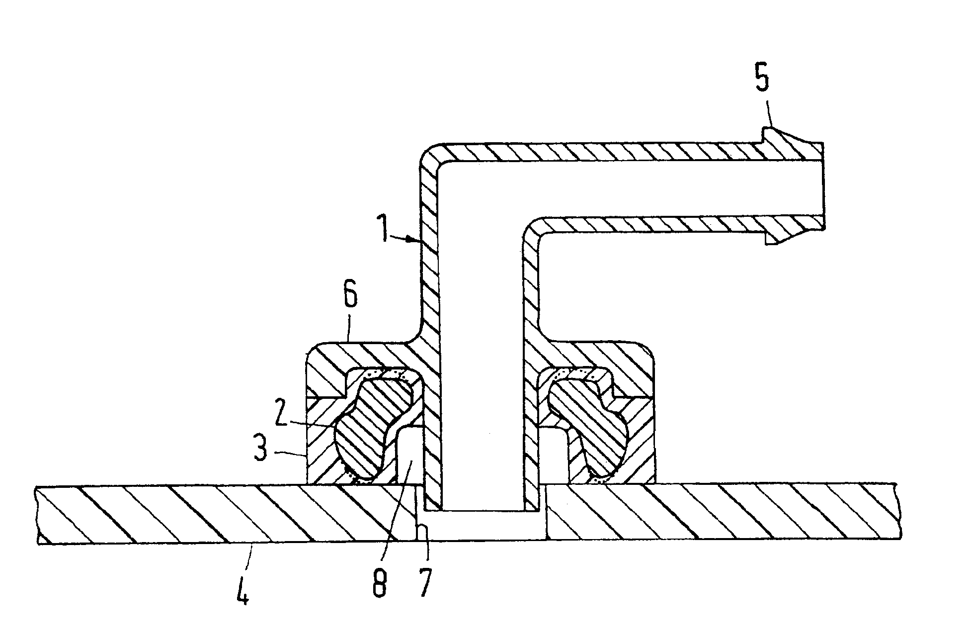
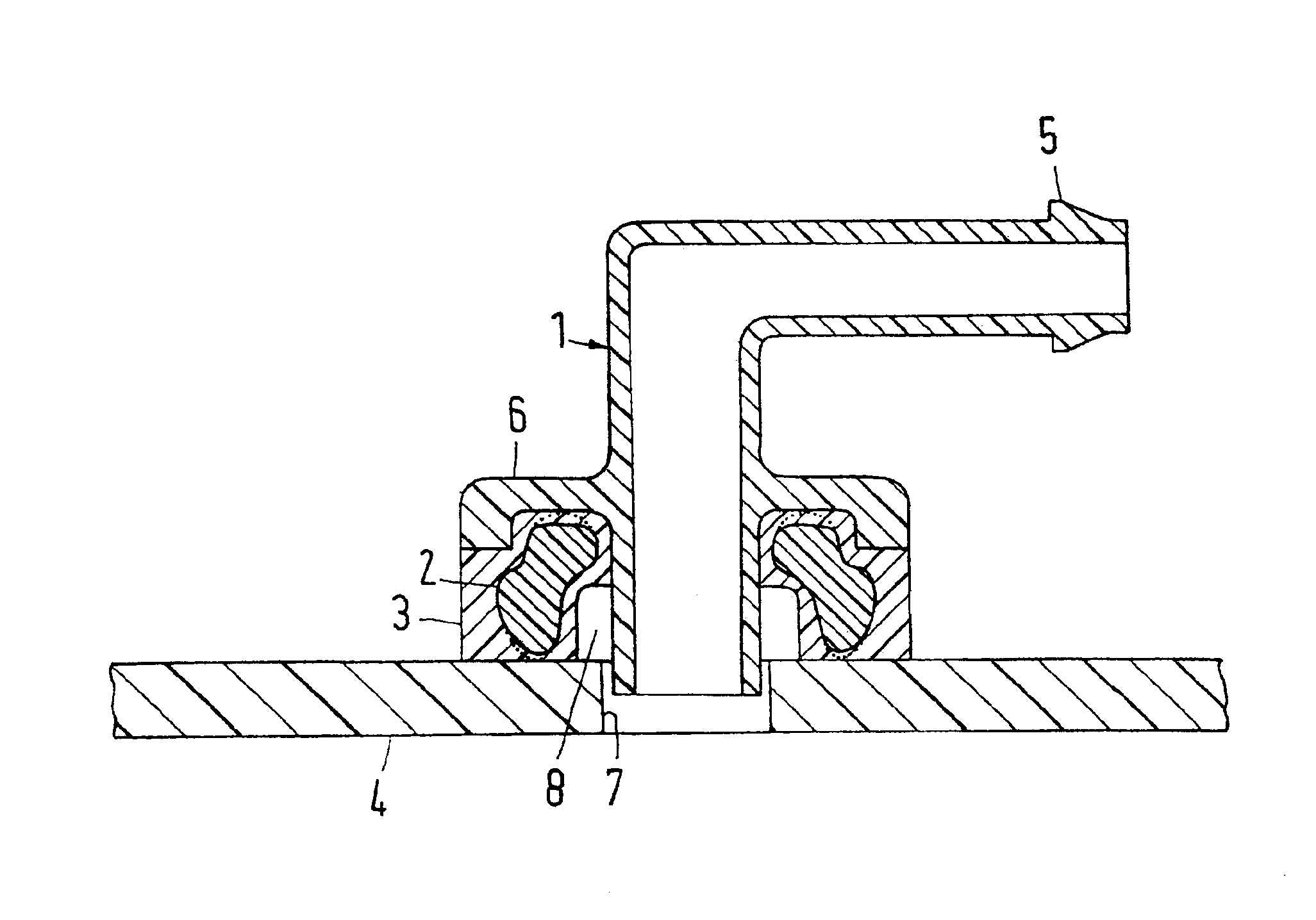
[0020]The coupling member, in detail, is comprised of a first component 1, a second component 2, and a third component 3 which are comprised primarily of a meltable material, in the illustrated example, primarily of thermoplastic material, and which are connected to one another in a material-bonding and positive-locking way. As an alternative, they could be connected either by material bonding or by a positive-locking connection.

[0021]The component 3 and the fuel-carrying part 4 are also connected by material bonding by means of friction welding or heat reflector welding wherein this type of welding or fusing results in a heat fusion joint or connection between the component 3 and the part 4.

[0022]The component 1 is a substantially tubular socket which is angled at 90Ε and provided with a securing rib 5 in the vicinity of its end across which a hose is pushed and secured on the pipe socket by means of a hose clamp. Instead of only a single securing rib 5, it is also possible to prov...


PUM

PropertyMeasurementUnit
densityaaaaaaaaaa
permeabilityaaaaaaaaaa
swelling capacityaaaaaaaaaa

Abstract

A coupling member for connecting a part, provided for receiving or dispensing fuel and made primarily of HDPE (high-density polyethylene), to a fluid line has first, second, and third components made of meltable material. The third component forms a heat fusion joint with the part for receiving or dispensing fuel and has an undesirably high permeability and swelling capacity relative to fuel. The third component is connected to the first component by material bonding and positive-locking action. The second component has greater fuel blocking capacity and higher strength than the third component. The second component is embedded in the third component. A volume ratio of second and third components is selected such that combined properties of the second and third components concerning permeability, strength, and volume changes by swelling are approximated to these same properties of the second component. The first and third components are heat-fusible to one another.

Description

BACKGROUND OF THE INVENTION[0001]1. Field of the Invention[0002]The invention relates to a coupling member, in particular, a pipe-shaped socket, for connecting a part, provided for receiving or dispensing fuel and made primarily of HDPE (high-density polyethylene), to a fluid line, wherein the coupling member has first, second, and third component of primarily meltable material, in particular, thermoplastic material, of which the third component forms a heat fusion joint with the fuel-carrying part and has an undesirably high permeability and swelling capacity relative to fuel and is connected to the first component in a material-bonding and / or positive-locking way, while the second component has a greater blocking capacity relative to fuel and a higher strength than the third component. The invention is also directed to a method for manufacturing the coupling member.[0003]2. Description of the Related Art[0004]In a known coupling member (DE 195 35 413 C1) of this kind the first and...

Claims


Application Information

Patent Timeline
Patent Type & Authority Patents(United States)
IPC IPC(8): B29C45/16B60K15/035B60K15/03F16L47/28F16L47/00B29C65/02F02M37/00F16L41/08F16L47/02
CPCB29C45/1642B29C66/53247B60K15/03519F16L47/28B29C65/02B29C2045/1648B29C2045/1654B60K15/035B29L2031/7172B29C66/1122B29C66/12445B29C66/12449B29C66/12469B29C66/131B29C66/71B29K2081/04B29K2077/00B29K2071/00B29K2067/006B29K2067/003B29K2067/00B29K2059/00B29K2027/12B29K2023/12B29K2023/065
Inventor KERTESZ, JANOS
Owner NORMA GERMANY GMBH
Why Eureka
Try Eureka