Internal combusion engine

a combustion engine and combustion chamber technology, applied in the direction of machines/engines, spark plugs, mechanical equipment, etc., can solve the problems of small penetration of flame ejected from the through hole, inability to reach the vicinity of the combustion chamber wall (cylinder bore wall), and unstable combustion of fuel-air mixture remaining, etc., to achieve the effect of burning stably

Inactive Publication Date: 2019-02-14
TOYOTA JIDOSHA KK
View PDF5 Cites 13 Cited by
  • Summary
  • Abstract
  • Description
  • Claims
  • Application Information

AI Technical Summary

Benefits of technology

[0015]Accordingly, in accordance with the present invention engine, the penetration of the flame (F1, F1a) ejected from the through hole with a longer “distance between the opening of the through hole and the region of the cylinder bore wall, which is opposed to the opening” (first through hole) is larger than the penetration of the flame (F2, F2a) ejected from the through hole with a shorter “distance between the opening of the through hole and the region of the cylinder bore wall, which is opposed to the opening” (second through hole). Therefore, it is possible for the flame ejected from the first through hole to reach the vicinity of the cylinder bore wall, without the flame ejected from the second through hole colliding with the cylinder bore wall strongly more than needed. As a result, by the flame ejected from the ignition chamber, fuel-air mixture can be burned stably in the main combustion chamber.
[0029]In accordance with this aspect, since fuel is directly injected into the ignition chamber, a “fuel-air mixture having an easily ignitable air-fuel ratio” can be easily formed inside the ignition chamber with less fuel. Therefore, even when an air-fuel ratio of a fuel-air mixture formed in the whole combustion chamber (the ignition chamber and the main combustion chamber) is increased, combustion can be generated stably and efficiency of the engine can be raised.

Problems solved by technology

However, in the conventional engine, since the bore of the through hole, through which flame is ejected to the region where the above-mentioned distance is long, is large, the penetration of the flame ejected from the through hole is small and there is a possibility that the flame may be unable to reach the vicinity of the wall of the combustion chamber (cylinder bore wall).
When the flame cannot reach the vicinity of the wall of the combustion chamber, there are problems such as unstable combustion of fuel-air mixture remaining in a region where flame cannot reach becomes unstable and / or an occurrence of knocking due to self ignition of the fuel-air mixture in the region.

Method used


Image

  • Internal combusion engine
  • Internal combusion engine
  • Internal combusion engine

Examples


first embodiment

(Configuration)

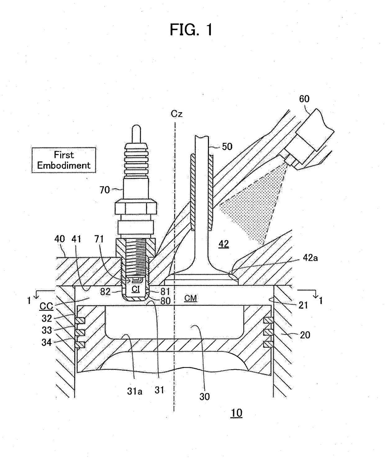
[0044]As shown in FIG. 1, an engine 10 according to a first embodiment of the present invention comprises a cylinder block 20, a piston 30, a cylinder head 40, an intake valve 50, a fuel injection valve 60, a spark plug 70 and a partition wall part (barrier) 80. Furthermore, the engine 10 comprises an exhaust valve which is not illustrated in FIG. 1. In addition, FIG. 1 is a longitudinal section of a specific cylinder, and other cylinders also have the same structure as the architecture shown in FIG. 1.

[0045]The cylinder block 20 comprises a cylinder bore wall 21. The cylinder bore wall 21 forms a cylinder bore in the shape of a cylinder. In addition, a cylinder liner may be attached to the cylinder bore. In that case, the cylinder liner also constitutes a part of the cylinder bore wall.

[0046]The piston 30 has an approximately columnar shape and is housed in the cylinder bore. A cavity 31a is formed in a part (which will be referred to as a “piston crown surface part”...

second embodiment

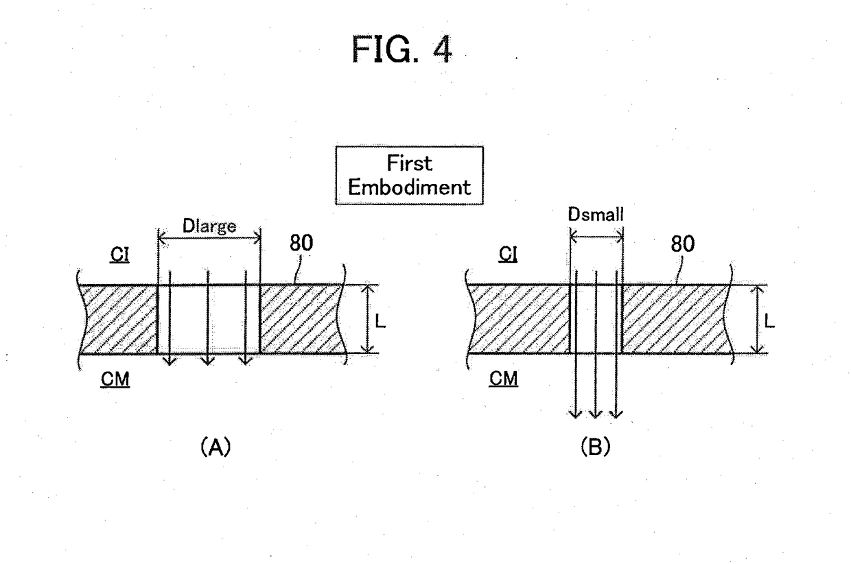
[0076]As shown in FIG. 5 and FIG. 6, an engine according to the second embodiment of the present invention is different from the engine 10 according to the first embodiment only in a point that the engine comprises a partition wall part 90 in place of the partition wall part 80 which the engine 10 according to the first embodiment comprises. More specifically, the thickness of the partition wall part 80 was the fix length L. On the contrary to this, the thickness of the partition wall part 90 changes (varies) in its circumferential direction. Furthermore, a plurality of through holes, which the partition wall part 90 comprises, has a diameter of the same length as one another. Hereafter, explanations will be added focusing on such differences.

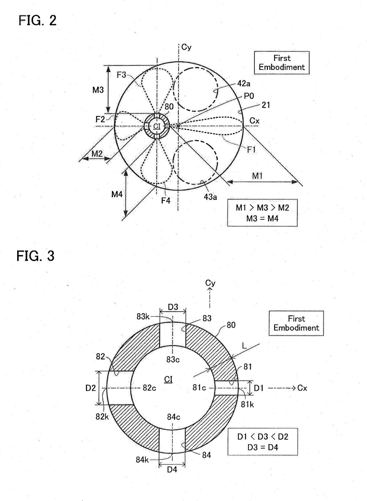
[0077]The partition wall part 90 comprises four through holes (the first through hole 91, the second through hole 92, the third through hole 93, and the fourth through hole 94) like the partition wall part 80. The shape of these through holes 9...

first modification

(First Modification)

[0098]In order to strengthen the penetration of the flame ejected from the through hole, as shown in (B) of FIG. 8, the shape of the end on the side of the ignition chamber CI of the through hole (edge of the entrance side opening) may be a curved surface R. In accordance with this, the swirls generated a the flame (fuel-air mixture under combustion) which flows from the ignition chamber CI into the through hole flows into the through hole can be weakened as compared with the case where the edge on the entrance side opening is a right angle shape as shown in (A) of FIG. 8. Therefore, when the shape of the edge on the entrance side opening is a curved surface shape, the swirls of the flame attenuate (disappear) before reaching the exit of the through hole (opening on the side of the main combustion chamber CM). Therefore, the flame ejected from the exit of the through hole into the main combustion chamber CM will not spread. As a result, the penetration of the fla...


PUM


Abstract

An internal combustion engine 10 comprises a spark plug 70 which has a spark generation part 71, and a partition wall part 80. The partition wall part 80 partitions a combustion chamber CC into a main combustion chamber CM and an ignition chamber CI. The combustion chamber is defined by a cylinder bore wall 21, a piston crown surface part 31 and a cylinder head wall 41. The cylinder bore wall and the piston crown surface part are exposed to the main combustion chamber, and the spark generation part is exposed to the ignition chamber. “A through hole 81 and a through hole 82” are formed in the partition wall part such that the main combustion chamber and the ignition chamber are in communication with each other. Flame is generated in the ignition chamber when combustion of fuel-air mixture is started by a spark generated from the spark generation part in the ignition chamber. The flame is ejected from the ignition chamber into the main combustion chamber through the first and second through holes. Distance between the first through hole and the cylinder bore wall is longer than distance between the second through hole and the cylinder bore wall. The first and second through holes are formed such that penetration of the flame ejected from the first through hole is larger than penetration of the flame ejected from the second through hole.

Description

TECHNICAL FIELD[0001]The present invention relates to an internal combustion engine configured to generate flame in an ignition chamber, to which a spark plug is exposed, and inject the flame from the ignition chamber to a main combustion chamber.BACKGROUND ART[0002]In one of internal combustion engines known conventionally (which may be referred to as a “conventional engine” hereafter), an ignition chamber, in which combustion of fuel-air mixture is started by a spark generated by a spark plug, is formed in a combustion chamber with a plug cover which covers an ignition point (spark generation part) of the spark plug. The region other than the ignition chamber in the combustion chamber may be referred to as a “main combustion chamber” for convenience. The conventional engine is configured to eject (spout) the fuel-air mixture which has started combustion in the ignition chamber (namely, flame or gas under combustion) from the ignition chamber into the main combustion chamber throug...

Claims


Application Information

Patent Timeline
Patent Type & Authority Applications(United States)
IPC IPC(8): F02B19/18F02B19/10
CPCF02B19/18F02B19/1023F02B19/108F02B19/12F02B23/08F02M61/145H01T13/54Y02T10/12
Inventor ASHIZAWA, TAKESHI
Owner TOYOTA JIDOSHA KK
Why Eureka
Try Eureka