Propulsion system for a ship or seagoing vessel

a technology for propelling systems and seagoing vessels, applied in marine propulsion, vessel parts, vessel construction, etc., can solve the problems of relatively inefficient prior art marine drives for ships and yachts, fuel consumption, etc., and achieve the effect of low speed, high fuel consumption, and low speed

Inactive Publication Date: 2009-02-26
HAGAN JAMES
View PDF21 Cites 10 Cited by
  • Summary
  • Abstract
  • Description
  • Claims
  • Application Information

AI Technical Summary

Benefits of technology

[0032]Engines for small ships and yachts are able to generate significant thrust. However, prior art marine drives for ships and yachts are relatively inefficient with low speed and high fuel consumption. Such ships and yachts are most efficient at lower speeds where the hull is plowing. Incremental increases in screw RPM are not matched by equivalent incremental hull speeds. This is because, when plowing, a ship's hull must displace ever greater bow wave mass as speed increases and such mass increases non-linearly with hull speed. The present invention provides a solution to this problem enabling larger craft to move more quickly through the water while using relatively less fuel to do so.
[0033]By changing the angle of attack of a ship's drive screws the hull may be raised in the water so that it displaces less water and produces a smaller bow wave. To achieve greater screw thrust, dual in-line screws are used with counter-rotation to provide a significant improvement in thrust without producing undesirable screw steering effects. However, because a change in angle of attack of a ship's screws to provide hull lift is sub-optimal in producing forward thrust, the first effect tends to be negated by the second effect. To overcome this problem, the screws used for lift are able to be placed at an optimal angle for doing so, while a third screw is positioned for maximum forward thrust. To provide for simplicity and economy of enabling this capability, all three screws are driven by a single drive shaft. The present invention reduces fuel consumption while permitting relatively higher speeds in larger boats and yachts.

Problems solved by technology

However, prior art marine drives for ships and yachts are relatively inefficient with low speed and high fuel consumption.

Method used


Image

  • Propulsion system for a ship or seagoing vessel
  • Propulsion system for a ship or seagoing vessel
  • Propulsion system for a ship or seagoing vessel

Examples


Embodiment Construction

[0043]The above described drawing figures illustrate the described apparatus and its method of use in at least one of its preferred, best mode embodiment, which is further defined in detail in the following description. Those having ordinary skill in the art may be able to make alterations and modifications to what is described herein without departing from its spirit and scope. Therefore, it must be understood that what is illustrated is set forth only for the purposes of example and that it should not be taken as a limitation in the scope of the present apparatus and method of use.

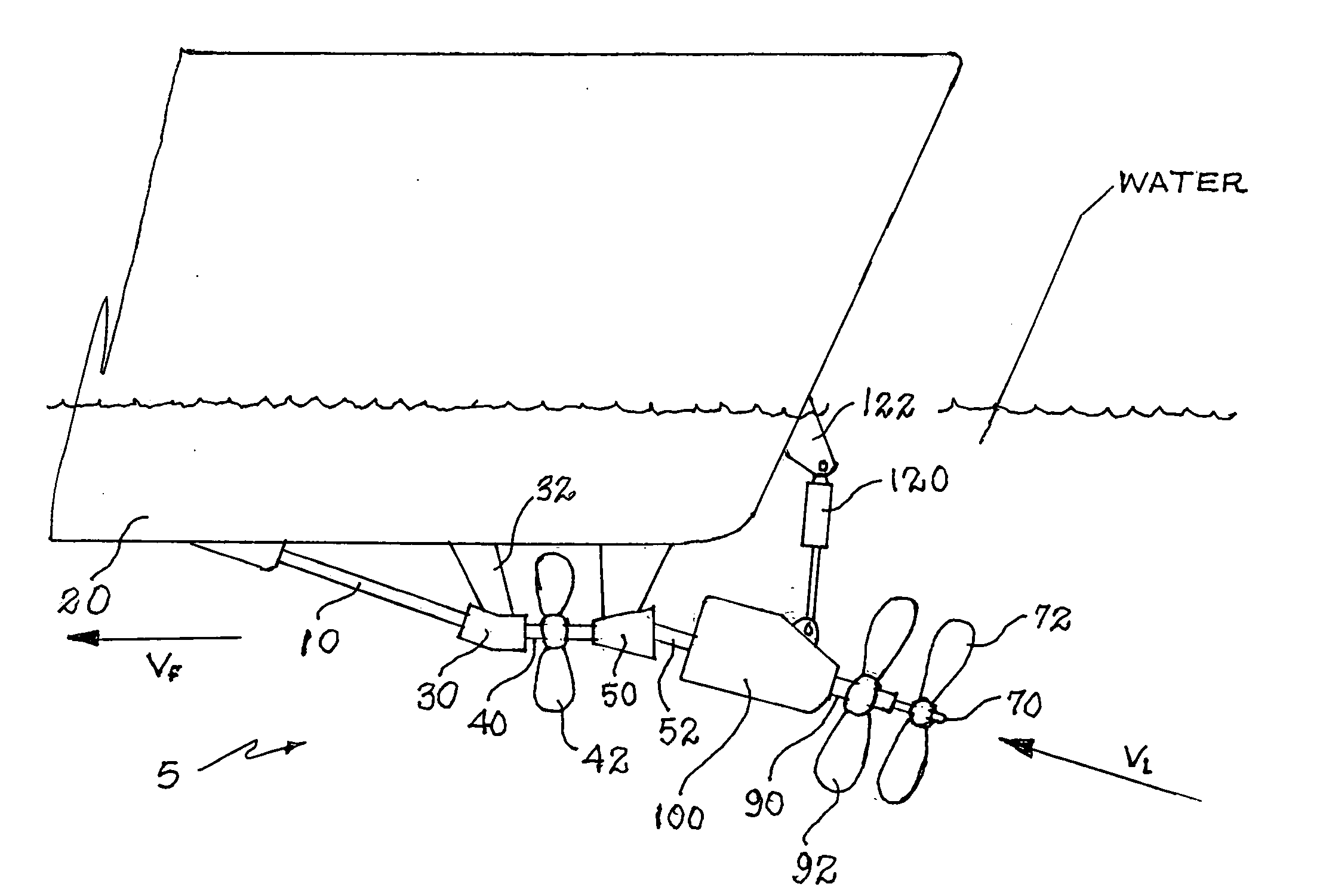
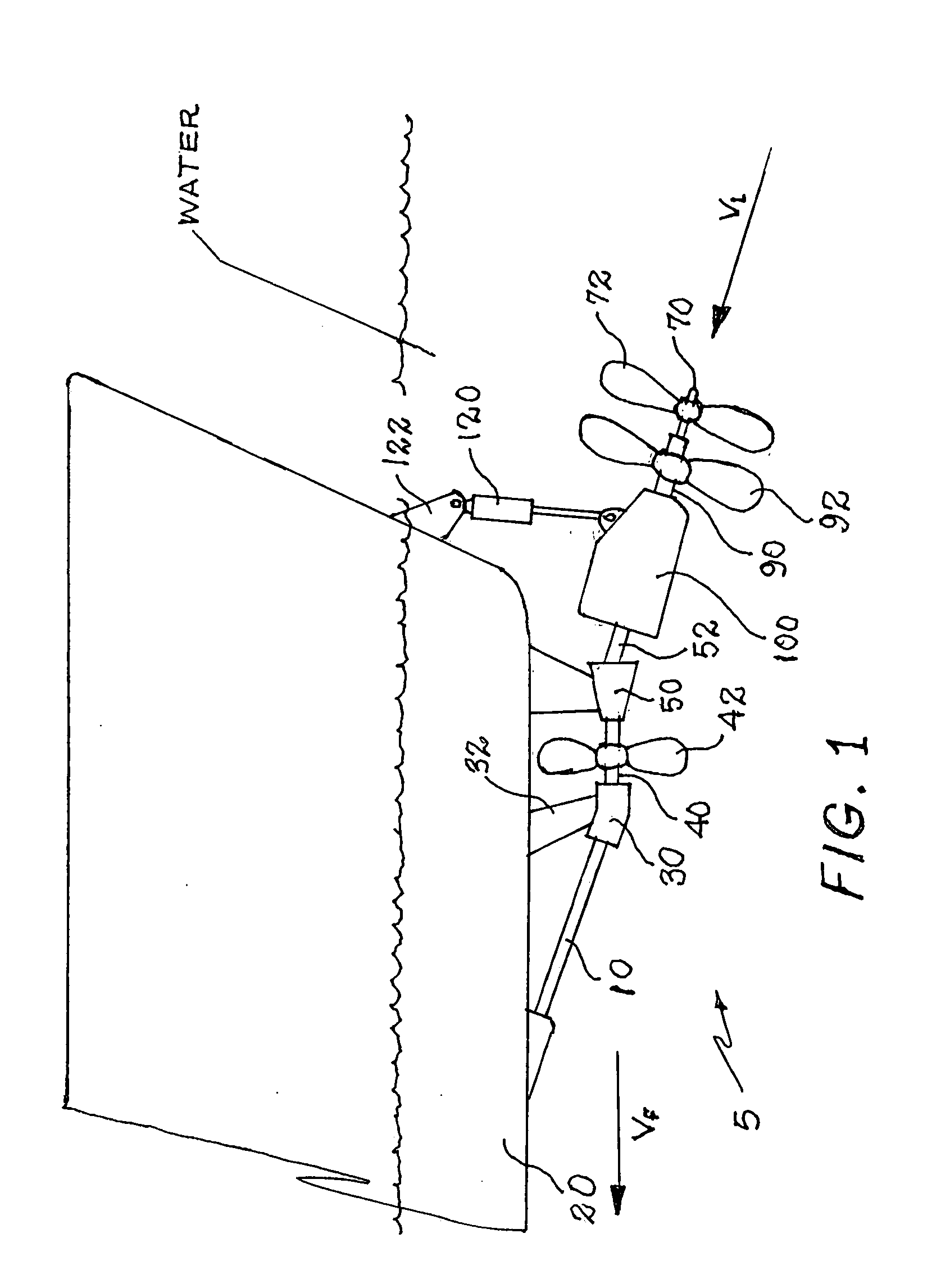
[0044]Described now in detail and shown in FIG. 1 is a marine drive apparatus 5 adapted for being engaged with and driven by an engine drive shaft 10 of a vessel. The vessel's hull 20 is penetrated by the engine drive shaft 10 which then extends rearwardly relative to the hull 20.

[0045]Referring still to FIG. 1, it is shown that the drive apparatus 5 includes a first universal joint 30 which is adapted b...


PUM


Abstract

A marine drive is engaged with and is driven by a vessel's engine drive shaft. The drive includes: a universal joint secured to the vessel's hull; a first screw shaft supporting a first screw; a first gear set driven by the first screw shaft; a second screw shaft driven by the first gear set; a second gear set driven by the second screw shaft; a third screw shaft driven by the second gear set and supporting a second screw; and a third screw supported by the second screw shaft at its terminal end. The first and second gear sets are enclosed within a water-tight enclosure enabling rotational speed differentiation between the first and second screw shafts and enabling rotational sense reversal between the second and third screw shafts. An actuator provides changes in angle of attack of the second and third screws.

Description

CROSS-REFERENCE TO RELATED APPLICATIONS[0001]Not applicable.STATEMENT REGARDING FEDERALLY SPONSORED RESEARCH OR DEVELOPMENT[0002]Not applicable.THE NAMES OF THE PARTIES TO A JOINT RESEARCH AGREEMENT[0003]Not applicable.INCORPORATION-BY-REFERENCE OF MATERIAL SUBMITTED ON A COMPACT DISC[0004]Not applicable.REFERENCE TO A “MICROFICHE APPENDIX”[0005]Not applicable.BACKGROUND OF THE INVENTION[0006]1. Field of the Present Disclosure[0007]This disclosure relates generally to marine drives, and more particularly to a marine drive capable of efficiently converting the output of powerful marine engines to forward thrust, to provide rotational speed differentials between plural screws driven by a single engine shaft, and to provide variable thrust vector angle of attack.[0008]2. Description of Related Art Including Information Disclosed Under 37 CFR 1.97 and 1.98[0009]Kirin, U.S. Pat. No. 1,595,949, discloses a boat comprising a hull having a cylindrical portion and keel supported centrally up...

Claims


Application Information

Patent Timeline
Patent Type & Authority Applications(United States)
IPC IPC(8): B63H23/00
CPCB63B3/42B63H5/10B63H2005/106B63H23/02B63H5/125
Inventor HAGAN, JAMES
Owner HAGAN JAMES
Why Eureka
Try Eureka