Machine tool for rotary machining

a technology of rotary machining and machine tools, which is applied in the direction of manufacturing tools, metal-working machine components, feeding apparatus, etc., can solve the problems of inaccuracy in tool adjustment and asymmetric heat transfer into the tool head, and achieve the effect of high machining accuracy and little force expenditur

Inactive Publication Date: 2016-01-05
KOMET GROUP GMBH +1
View PDF19 Cites 0 Cited by
  • Summary
  • Abstract
  • Description
  • Claims
  • Application Information

AI Technical Summary

Benefits of technology

[0003]Using this as the starting point, the invention is based on the object of providing a machine tool with a mechatronic assembly, especially for the remachining of valve seats on cylinder heads, which enables an adjustment of the mechatronic assembly with little expenditure of force and which ensures very high levels of machining accuracy.

Problems solved by technology

Furthermore, the side arrangement of the adjusting motor with regard to the rotational axis of the machine spindle results in an asymmetrical heat transfer into the tool head.
This leads to inaccuracies in the tool adjustment.

Method used


Image

  • Machine tool for rotary machining
  • Machine tool for rotary machining
  • Machine tool for rotary machining

Examples


Embodiment Construction

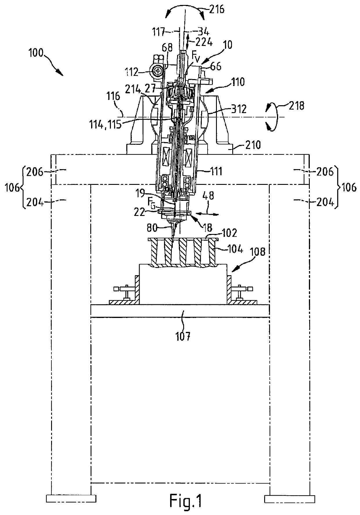
[0025]The machine tool 100 in FIG. 1 has a chucking device 108 for the cylinder head 104 of an internal combustion engine. The machine tool 100 includes a mechatronic assembly 10. The mechatronic assembly 10 has a tool head 18 with a cutting tool. The mechatronic assembly is located in a sleeve 111. The mechatronic assembly 10 is guided in the sleeve 111 in a linearly movable manner. Together with the sleeve 111, the mechatronic assembly 10 is mounted on a carrier device 106. The carrier device 106 comprises a machine base 206. The machine base 206 is a support for a guide block 210. The guide block 210 carries an articulated arrangement 110 for the mechatronic assembly 10. The articulated arrangement 110 is designed as an air cushion-supported ball joint 110. The ball joint 110 has a joint shell 312 which is formed in the guide block 210. The sleeve 111 for the mechatronic assembly 10 has a joint body 214. This joint body 214 has a spherical surface contour. The carrier device 106 ...


PUM

PropertyMeasurementUnit
weight forceaaaaaaaaaa
torqueaaaaaaaaaa
gravityaaaaaaaaaa

Abstract

A machine tool has a mechatronic assembly which has a machine spindle and has a tool head which is held on the machine spindle and which has a basic body and also at least one working slide, which is adjustable relative to the basic body, for holding a tool. The mechatronic assembly contains an electric adjusting motor which acts on the working slide. The machine tool has a support device which holds the mechatronic assembly and which has an articulated joint arrangement at which the mechatronic assembly can be pivoted at least about a first axis and about a second axis which differs from the first axis.

Description

FIELD OF THE INVENTION[0001]The invention relates to a machine tool for rotary machining, especially for machining valve seats on cylinder heads, with a mechatronic assembly which has a machine spindle, with a tool head mounted on the machine spindle, which tool head has a basic body and also at least one working slide, which is adjustable relative to the basic body, for the mounting of a tool, with an electric adjusting motor acting upon the working slide, and with a carrier device which accommodates the mechatronic assembly.BACKGROUND OF THE INVENTION[0002]Such a machine tool is known from FR 2 832 658 A1. This machine tool comprises a mechatronic assembly. The mechatronic assembly of the machine tool is accommodated on a carrier device. The mechatronic assembly includes a tool head. The tool head is connected to a machine spindle with a rotational axis. The tool head is designed with a guide pin. The tool head has an adjustable holder unit on which a cutting tool is fastened. For...

Claims


Application Information

Patent Timeline
Patent Type & Authority Patents(United States)
IPC IPC(8): B23Q5/32B23Q1/54B23Q11/00B23C3/05
CPCB23Q1/545B23C3/055B23Q1/5462B23Q11/001Y10T408/45Y10T409/30784Y10T409/307672Y10T409/308232Y10T409/309352
Inventor FRONIUS, JURGENSOQUET, MICHELMUGNIER, REMIBRAUN, KARL-HEINZ
Owner KOMET GROUP GMBH
Why Eureka
Try Eureka