Inverter circuit for suppressing electric power conducted interference

A technology of conduction interference and reflux, applied in the direction of instruments, static indicators, etc., can solve the problems of unstable working frequency, great influence on the normal image and audio performance of video products, and flickering of the first load, etc.

A technology of conduction interference and reflux, applied in the direction of instruments, static indicators, etc., can solve the problems of unstable working frequency, great influence on the normal image and audio performance of video products, and flickering of the first load, etc.

CN1755784AInactive Publication Date: 2006-04-05ZIPPY TECH

Image

  • Inverter circuit for suppressing electric power conducted interference
  • Inverter circuit for suppressing electric power conducted interference
  • Inverter circuit for suppressing electric power conducted interference

Examples


Embodiment Construction

[0015] Relevant detailed description and technical contents of the present invention are as follows now in conjunction with the accompanying drawings:

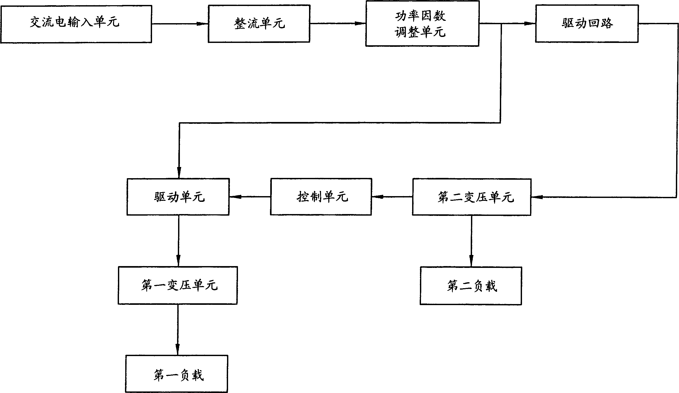
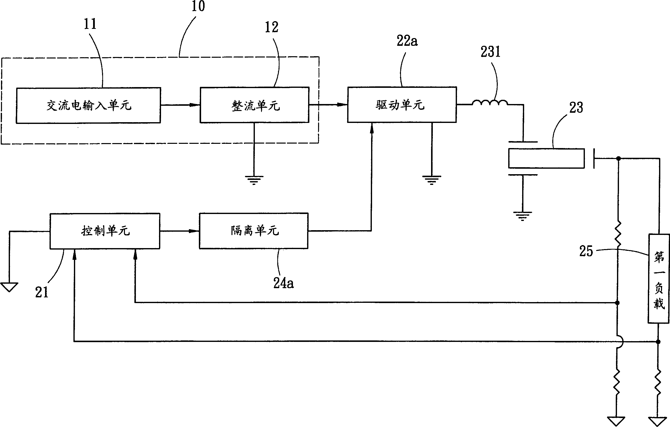
[0016] see image 3 , 4 As shown, the present invention outputs a power signal to an inverter circuit 20 from a power input loop 10, the power input loop 10 is an alternating current input unit 11, and a rectifying unit 12 that converts alternating current to direct current, and the reverse current The converter circuit 20 outputs a working frequency by a control unit 21, and receives the working frequency cutting power signal with a driving unit 22a and outputs a driving signal, and receives the driving signal with a first transformer unit 23 for power conversion to drive The first load 25 operates, and the first load 25 feeds back voltage and current signals to the control unit 21, wherein an isolation unit 24a is arranged between the drive unit 22a and the control unit 21, through the isolation unit 24a and the first trans...


PUM


Abstract

The invention discloses a reverse current device circuit to inhibit power conducted interference. Wherein, receiving output signal from power input circuit, outputting operating frequency; using a drive unit to receive said frequency and cut signal and output drive signal; using a transformation unit to receive said drive signal and take power conversion to drive first load action; arranging an isolation unit between drive and control units to divide grounding type of drive unit and control unit as non-share grounding with first and secondary sides of transformation unit. Thereby, the control unit outputs stable operating frequency and realize inhibiting effect.

Description

technical field [0001] The invention relates to an inverter circuit for suppressing electric power conduction interference, in particular to an inverter circuit for converting large and small currents and high and low voltage power at the same time. Background technique [0002] see figure 1 Shown is a schematic block diagram of the power supply circuit of video products such as traditional LCD screens or LCD TVs. When the video product is connected to the AC input unit of the mains, the AC power signal is input from the AC input unit, and the AC power signal passes through the diode The rectifier unit composed of the group performs power conversion and outputs a pulsed DC power signal, and then performs power factor correction by a power factor adjustment unit to become a regulated DC power signal, and the regulated DC power signal is output in parallel to an inverter ( inverter), and through the second drive circuit to a second transformation unit, the second transformati...

Claims


Application Information

Patent Timeline
05 Apr 2006
Publication
CN1755784A
IPC
G09G3/36; G02F1/133
Inventors
周进文; 郑英男