Power supply converting circuit system

A conversion device, a specific technology, applied in the power supply system, the field of understanding will be better, can solve the problem of electromagnetic interference filter circuit design difficulty, total harmonic distortion increase and other problems

Inactive Publication Date: 2005-08-10
KONINKLIJKE PHILIPS ELECTRONICS NV
View PDF0 Cites 0 Cited by
  • Summary
  • Abstract
  • Description
  • Claims
  • Application Information

AI Technical Summary

Problems solved by technology

[0008] If the power of the load 170 fluctuates greatly, the operating frequency of the system 110 will also fluctuate greatly, resulting in difficulties in the design of circuits related to the system 110, such as electromagnetic interference filtering circuits (EMI), and including power conversion circuits The total harmonic distortion (THD) of the entire working circuit including the system 110 will also have a large increase

Method used


Image

  • Power supply converting circuit system
  • Power supply converting circuit system
  • Power supply converting circuit system

Examples


Embodiment Construction

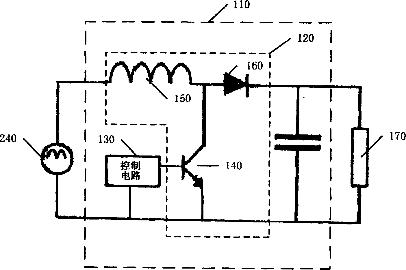
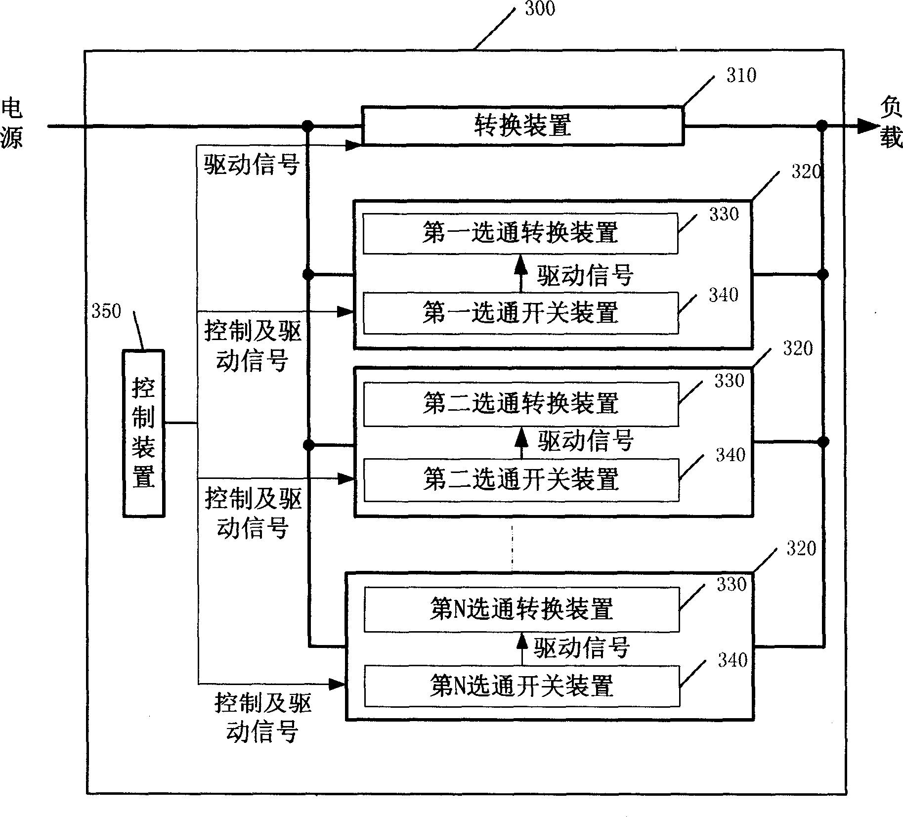
[0023] image 3 It is a block diagram of a power conversion circuit system 300 according to an embodiment of the present invention. The power conversion circuit system 300 includes a conversion device 310 and a plurality of gating devices 320 . Each gate means includes a gate switch means 330 and a corresponding gate switch means 340 . Switching device 310 and gate switching device 330 can be conventional switching circuits (such as figure 1 Circuit 120 shown).

[0024] The system 300 also includes a control device 350 for controlling the gate switch device 330 through the gate switch device 340 . As shown in the figure, the control device 350 sends a control signal to the gate device 320, selects and opens the corresponding gate conversion device 330 through the gate switch device 340, and drives the corresponding selected gate conversion device 330 through the gate switch device 340 with a driving signal. The gate switching means 330 works together with the switching mea...


PUM


Abstract

Operating together one or more strobe units turned on by stepping selection and conversion device, making operation of power supply change over undertaken by conversion device become stable relatively so as to make operation frequency of power supply change over system become stable. Thus, designing relevant circuits is easier than before.

Description

Background technique [0001] The invention relates to a power supply system, in particular to a power conversion circuit system. [0002] In electrical equipment, the application of power conversion circuits is very common, mainly used to meet the different requirements of different loads on power. The boost conversion circuit is a common power conversion circuit. [0003] The boost conversion circuit can convert the sine half-wave voltage input from the rectification circuit into a stable output voltage, so it is very suitable for the requirements of electrical equipment for regulated DC sources. figure 1 is a circuit diagram of boost conversion circuitry 110 . System 110 includes boost conversion circuit 120 and control circuit 130 . The boost conversion circuit 120 is composed of a semiconductor switch 140 , an inductor 150 and a diode 160 . [0004] The control circuit 130 is used to improve the power factor at the input of the system 110 . A commonly used control circ...

Claims


Application Information

Patent Timeline
Patent Type & Authority Applications(China)
IPC IPC(8): H02M7/12
Inventor 丁九良王磊
Owner KONINKLIJKE PHILIPS ELECTRONICS NV
Why Eureka
Try Eureka