
Complementary symmetrical self-excited push-pull converter

A self-excited push-pull, complementary symmetrical technology, applied in the field of power supply, can solve the problems of large influence of oscillation frequency, difficult cost reduction, poor frequency characteristics, etc., and achieve stable working frequency, reduced volume, and good consistency

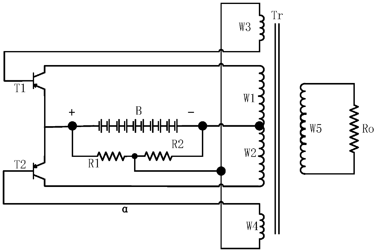
Pending Publication Date: 2020-03-27
雷博塔斯(广州)科技有限公司
View PDF1 Cites 0 Cited by
  • Summary
  • Abstract
  • Description
  • Claims
  • Application Information

AI Technical Summary

Problems solved by technology

[0010] a) Poor consistency of mass-produced products;
[0011] b) The frequency characteristics are poor, not stable enough, the oscillation frequency is greatly affected by the high-frequency transformer, and it is difficult to adjust the switching frequency;
[0012] c) The general frequency is not high, resulting in a large transformer size and difficult to reduce costs;

Method used


Image

  • Complementary symmetrical self-excited push-pull converter
  • Complementary symmetrical self-excited push-pull converter
  • Complementary symmetrical self-excited push-pull converter

Examples


Embodiment Construction

[0073] Specific embodiments of the present invention will be described in detail below.

[0074] Figure 8 It is a schematic diagram of an embodiment of a complementary symmetrical self-excited push-pull converter disclosed in the present invention. Such as Figure 8 As shown, a complementary symmetrical self-excited push-pull converter, including:

[0075] DC power supply V1, the negative pole of which is grounded;

[0076] Capacitor C1, one end of which is grounded, and the other end of capacitor C1 is connected to the positive pole of DC power supply V1;

[0077] Resistor R1, one end of which is connected to the positive pole of DC power supply V1;

[0078] Resistor R2, one end of which is connected to the positive pole of the DC power supply V1;

[0079] NPN transistor Q1, its C collector is connected to the other end of resistor R1, and the E emitter of NPN transistor Q1 is grounded;

[0080] NPN transistor Q2, its E emitter is grounded, and the C collector of NPN t...


PUM


Abstract

The invention relates to a complementary symmetrical self-excited push-pull converter. The converter comprises a direct-current power supply V1, a capacitor C1, a resistor R1, a resistor R2, an NPN transistor Q1, an NPN transistor Q2, a resistor R3, a resistor R4, a capacitor C2, a capacitor C3, an NPN transistor Q3, an NPN transistor Q4, a high-frequency transformer T and a filter inductor Lf. The complementary symmetrical self-excitation push-pull converter disclosed by the invention has the following beneficial effects: 1, the consistency of products produced in batches is good, and the influence of high-frequency inductance is small; 2, the working frequency of the switching tube is stable; 3, the self-oscillation frequency can be designed to be relatively high, and correspondingly, the size of the high-frequency transformer is reduced, so that the cost is reduced; and 4, due to the driving of the independent self-excited oscillation circuit, the working power of the switching tubecan be selected to be greater.

Description

technical field [0001] The invention belongs to the field of power supplies, and mainly relates to switching power supplies, inverters, spark generators, frequency converters, electric welding machines, industrial control and lighting industries, and in particular to a complementary symmetrical self-excited push-pull converter. Background technique [0002] The circuit structure of the existing self-excited push-pull converter comes from the self-excited oscillating push-pull transistor single-transformer DC converter invented by George H. Initially, the above-mentioned circuit form is the famous Royer circuit. [0003] In 1958, T.Hehenkamp and J.J.Wilting described a modified Royer-style self-excited push-pull circuit in "Transistor D.C converters for Fluorescent-Lamp Power Supplies", specifically as figure 1 shown. [0004] In 1963, Ludwig (H. Ludwig) described a Royer-style self-excited push-pull circuit in "A time and voltage calibrator for biological amplifiers using ...

Claims


Application Information

Patent Timeline
Patent Type & Authority Applications(China)
IPC IPC(8): H02M7/538
CPCH02M7/538
Inventor 许超曹世昌
Owner 雷博塔斯(广州)科技有限公司
Learn More